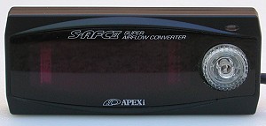
These instructions will help you adjust the A'PEXiS-AFCII Super Airflow Converter in the Mitsubishi 3000GT VR4 and Dodge Stealth R/T Twin Turbo. The control unit pictured to the right is the "black on black" model. Other color combinations are available: silver case with blue display, silver case with black display. These web-page instructions are specifically for the 1992 3000GT/Stealth DOHC Turbo. However, they can be used for all other DOHC model years by selecting the correct engine control unit (ECU) wires for the target 3S model. In addition, my 1992 Dodge Stealth TT already had an ARC2-GP hot-wire mass airflow sensor (MAS) conversion installed (as well as other electronics that tapped into the ECU harness). The S-AFCII was installed inline "after" the ARC2-GP. For installation instructions see my web page 2-safcii-instal.htm.
The S-AFCII intercepts the air flow signal (volume or mass) and increases or decreases it before the engine control unit (ECU) "sees" the signal. This can be used to compensate for larger-than-stock fuel injectors and to fine-tune the air-fuel mixture. The S-AFCII can be used with engines that have a "hot-wire", "flap", or pressure mass air flow sensor (single or dual), or the Karman-type volume air flow sensor, which is installed on 3000GT/Stealth (3S) engines. I am not sure how, or if, the control unit can distinguish between a frequency-based hot-wire MAS (for example many GM MAS's) or a voltage-modulated hot-wire MAS (for example many Ford MAS's). In any case, these instructions assume the S-AFCII is intercepting a Karman-type volume air flow signal. Therefore, it can be used with the stock 3000GT/Stealth MAF or after a hot-wire conversion (ARC2-GP, MAF-T, PRO-M). The S-AFCII cannot be used to convert a mass flow signal to a volume flow signal, that is, it cannot be used to convert the signal from a Ford or GM MAS to the Karman signal required by our ECU. For our car, the signal going into the S-AFCII must be a Karman signal (a frequency modulated square-wave) so that the S-AFCII sends a Karman signal to our ECU.
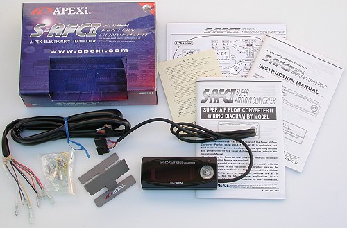
The A'PEXi S-AFCII "kit" consists of the items shown in the photograph below: the control unit, a wiring harness, manuals and instructions, a mounting bracket, some electric coupling pieces, and a little bit of Velcro. I paid $300 (includes shipping) for this black case/black display special edition model from seller tri-band-mobile (also a 3000GT owner) on eBay in August 2003.
The A'PEXi S-AFCII is an airflow signal converter that has the following features and functions when installed on our DOHC models, which send a Karman-type airflow signal to the ECU.
Thin-case design: 5" wide, 2" high, 0.7" deep. An optical sensor is on the front of the case (upper right corner) to optionally automatically adjust display brightness.
A dot matrix Vacuum Fluorescent Display (VFD) for graphical and numeric real-time parameter display. Analog-type gauges can be displayed. Up to four parameters can be monitored at one time, with peak recall and 15-second replay. Parameters can be engine rpm, Karman frequency, throttle position percent, knock sensor output, airflow correction setting, and battery voltage.
Front panel control consisting of a rotary switch with a 4-direction/push-button switch in the center of it.
EEPROM memory to maintain settings when power is disconnected from the unit.
Optional password protection of settings.
Capability to store two patterns of settings in memory.
Twelve rpm set points from 800 rpm to 9800 rpm, with 200 rpm steps.
Separate airflow correction factors, from -50% to +50% with 1% steps, at each rpm set point for Low and High throttle openings. There is a "graphic equalizer" type display of correction factors.
Monitors engine rpm, throttle position, input airflow signal (Karman frequency), battery voltage, and knock sensor.
Warning mode (display blinks) based on selected monitored parameter.
These instructions supplement those provided by A'PEXi. Please read all of this web page before beginning this installation procedure. Also, before installing the S-AFCII, read through the Wiring Diagram and Instruction manuals to familiarize yourself with the S-AFCII installation and operation
Reality Check
One of the main reasons for installing the S-AFCII, or any other airflow signal interceptor (ASI) such as the HKS Super AFR or GReddy e-Manage, or a MAS conversion kit (Split Second ARC2-GP, Full Throttle Speed & Style MAF-Translator, PRO-M Karman-Vortex Air Meter Conversion Kit, Performance Motor Research MAP-ECU, HKS Vein Pressure Converter), or one of the "standalone" setups (AEM, for example), is because you have installed larger injectors and larger turbos on your car. And, more than likely, you have also installed a boost controller. By using the devices listed above, you have taken on the responsibility of protecting your engine from damage or destruction.
Let me say this another way. The ECU for the factory setup has several built-in safety features. You are eliminating these by installing an ASI, MAS converter, or standalone system. The ECU is designed (programmed) to not let the engine run lean. In fact, our engine tends to run a little too rich during boost. A safety feature. The ECU monitors engine knock and tries to reduce or eliminate it by reducing boost, by reducing timing, and by adding extra fuel. Safety features. The ECU monitors engine load and if it guesses that too much air is flowing, that is, that boost is too high, it cuts fuel to the engine. A safety feature, albeit an annoying one. The ECU also manages the air-fuel mixture during low engine loads using a feedback system to minimize exhaust emissions. This is not strictly a safety feature but does provide the benefits of reduced carbon build-up and increased gas mileage.
When you install a boost controller you deny the ECU the ability to reduce boost in response to knock. When you install an ASI or MAS converter you are telling the ECU that a different amount of air is flowing than there really is. This means the ECU cannot accurately control the air-fuel mixture for the real set of engine operating conditions, leading perhaps to a dangerous lean condition. Because airflow reported by the ASI is less than actual flow when larger injectors are installed, the ECU thinks engine load is less and so may keep timing advance higher than it should and may use a different target air-fuel ratio during acceleration.
Part of your new responsibilities for engine management will be to learn how the ECU works with a factory setup, that is, before you install the S-AFCII and larger injectors. For fuel management and ignition control, you can start with my web pages 2-fuelinjection.htm and 2-ignitionsystem.htm. Next, you can use a datalogger to observe and record how the ECU acts and reacts during a variety of engine operating conditions: cold start, warm-up, warm idle, low and moderate engine load cruising (closed-loop operation, more on this later), moderate and high engine load acceleration (open-loop operation, more on this later), low boost vs. high boost (differences in timing and knock). Start logging and just drive around like you normally do, including stop, start, idling, cruising at different speeds, and acceleration. In the "Adjusting the S-AFCII" section below I'll tell you what to look for in these datalogs.
Available Dataloggers
Dataloggers are available for all years of 3000GT and Stealth. For 1991-1993 (OBDI) models there are the following.
Full Throttle Speed & Style Scanmaster 3 (absolutely my favorite, 3S-specific monitoring and many extra features not found in the other dataloggers, does not need a laptop or handheld computer, can send output to a Windows OS or Palm OS computer with datalogger software)
Digital Tuning, Inc. PocketLOGGER (dependable data with 3S-specific monitoring, only 12 values can be recorded at one time, very nice playback viewer; for Palm OS)
Mirage Corporation OBDI Datalogger (good stuff, innovative, could still use some refinement for 3S-specific data, 16 values can be recorded at one time; for Palm OS)
MMCd freeware (it's free and it's good! can still use some refinement, all values can be recorded at one time, for Palm OS)
Tunerstein and Palm'n'Stein (old, crude, outdated, no 3S-specific functions, but it's free; for Windows OS and Palm OS)
Mitsubishi MUT and Chrysler DRB tools (expensive factory items)
For 1994-1995 (OBDI-hybrid) models there is the Mirage Corporation Hybrid Datalogger and the DRB/MUT tools. For 1996 and newer models (OBDII) there are a large number of OBDII dataloggers available plus the DRB/MUT tools. See my Datalogging Links for selected OBDII dataloggers and more info about datalogging (all years).
Initial Setup of the S-AFCII
After installing the S-AFCII, read through the Instruction Manual again to familiarize yourself with the operation of the S-AFCII. If you did not receive an Instruction Manual with your S-AFCII the manual is available at http://www.apexi-usa.com/documentation.asp.
Turn the ignition switch to "ON". The S-AFCII will turn on automatically; there is no On/Off switch on the control unit. Do not attempt to start the engine until the Initial Setup procedure is completed. The following items must be set.
Mass airflow sensor type (Karman; no other choice can work for our ECU).
Number of cylinders (6, of course).
Throttle sensor type (0-1 V closed, 3-5 V wide open; the arrow in the menu will point up and to the right).
Throttle opening self learn (closed will be 0%; wide open will be 100%). These percentages are used to set Low Throttle and High Throttle correction factors at each rpm set point (called "Ne" points). These percentages are different than the Throttle Position Sensor percentage displayed by dataloggers. The percent displayed by dataloggers is the TPS voltage divided by 5.0 V and multiplied by 100. Typical TPS closed voltage is 0.5-0.6 volts (10-12%); any voltage less than 1 V (or 20%) is OK and tells the ECU that the throttle is closed. There is also an Idle Position Switch. Typical wide open TPS voltage is 4.7-5.0 volts (94-100%); any voltage more than 4 V indicates to the ECU that a WOT situation exists.
Selecting items in a menu is performed using the 4-direction switch. Move the switch up to move up the menu list (or to the last item if at the top of the list). Move the switch down to move down the menu list (or to the first item if at the end of the list). For some menus, turning the rotating switch can select an item. To choose an item press the 4-direction switch in (not left, right, up, or down) or move it to the right (choose "Nx"). Move the 4-direction switch to the left (choose "Pr") to return to a previous menu.
There are diagrams and explicit instructions in the S-AFCII Instruction Manual. I am not going to repeat the very clear steps for setting each of the above four parameters that are in the S-AFCII Instruction Manual. After the Initial Setup procedure is completed, turn the ignition off. It will take a few seconds for the S-AFCII to turn itself off after the ignition is turned off.
Adjusting the S-AFCII
Here is a summary of what needs to be done after the initial setup and the order to do it. I'll discuss each of these in more detail below.
Select/set Lo and Hi throttle opening settings.
Select/set the Ne (rpm) points.
Select/set initial air correction factors based on injector size.
Start engine (car parked) and adjust air correction factors for the Lo throttle opening at the Ne points.
Drive car with low engine load (ECU closed loop mode) and adjust air correction factors for the Lo throttle opening at the Ne points.
Drive car with higher engine load (ECU open loop mode) and adjust air correction factors for the Hi throttle opening at the Ne points.
While driving car over the next few days make fine tuning adjustments as necessary.
A'PEXi calls the rpm set points "Ne points". The term "Ne" is from the Toyota name for their engine revolution sensor, a device separate from the crank angle sensor. "Ne" stands for "Number of engine revolutions".
Tools needed
I recommend using the following tools to help you adjust the S-AFCII. The adjusting mentioned here does not include the knock detection feature. I'll make a separate web page for that.
A datalogger. Dataloggers report engine rpm, throttle position, front (right) and rear (left) O2 sensor voltages, knock count (a measure of detonation), air flow (in Hz), injector pulse width (in milliseconds), and many more ECU parameters. Some dataloggers (like Scanmaster 3) also report vehicle speed and acceleration, boost pressure, and EGT. The last two parameters require aftermarket gauges.
At least one exhaust gas temperature (EGT) gauge, but preferrably two (see 2-egtpyrometers.htm).
Two O2 meters (one for each O2 sensor), or better yet, one or two wide-band oxygen sensors with their monitoring meters.
An aftermarket boost gauge (it can be part of an electronic boost controller).
ECU FUEL CONTROL MODES
To determine the amount of fuel to inject, the ECU first compares the volume air flow to the engine speed and calculates a basic injector activation time. Next, the ECU selects one of two different modes, feedback control or preset map control, to modify the basic activation time. Finally, the activation time is adjusted based on engine speed, engine coolant temperature, intake air temperature, barometric pressure, and battery voltage (see 2-fuelinjection.htm). This section explains feedback fuel control and preset map fuel control. Being able to identify when the ECU is in one or the other is critical for adjusting the S-AFCII.
ECU closed-loop fuel injection control (feedback control)
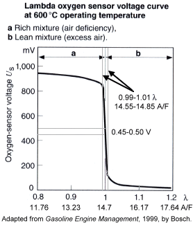
In closed-loop mode, the ECU is using oxygen sensor voltage (see figure below) in a feedback loop to restrict the air-fuel ratio to a narrow range where the catalytic converter is most efficient. That range is A/F equal to 14.7 plus or minus 1% air (0.99-1.01% lambda, where a theoretical lambda of 1.0 equals an A/F of 14.7), or ~14.55 to ~14.85 A/F. The oxygen sensor indicates a (theoretical) stoichiometric air-fuel mixture (A/F equal to ~14.7) with a voltage typically in the range of 0.45 to 0.5 volts. When the sensor output is greater than this range, there is much less oxygen in the exhaust gas than in the atmosphere and the mixture is rich (A/F is less than ~14.7). When there is excess oxygen concentration in the exhaust gas, that is, as the oxygen content approaches that of the atmosphere, the sensor sends a signal less than 0.45 to 0.50 volts to indicate a lean mixture (A/F is greater than ~14.7). If fuel injection is stopped in the engine, oxygen content in the exhaust stream will equal that in the atmosphere and the O2 sensor voltage output will be zero. Typically the ECU uses a reference voltage of about 0.4 V, which is just on the lean side of ~14.7. The ECU reacts to these rich and lean signals by reducing and increasing, respectively, the injector activation duration. By using this feedback control to maintain the oxygen content in the exhaust stream within a very narrow range, the three-way catalytic converter operates at its peak efficiency to reduce carbon monoxide (CO), hydrocarbon (HC), and nitrous oxides (NOx) emissions.
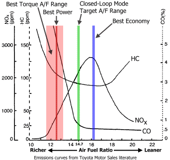
Closed loop mode is used generally during warm idle, low-load cruising, and low-load acceleration to reduce engine emissions. Best fuel economy actually occurs with a slightly lean mixture, with A/F a little more than 16. Despite the need to reduce emissions, there are certain operating conditions where closed loop mode is not used in order to prevent overheating the catalytic converter or driveability problems. These situations include:
While cranking the engine.
During engine warmup when the coolant temperature is below 45ºC (113ºF).
During strong acceleration or deceleration.
During high-load operation.
When the oxygen sensor is not functioning properly.
ECU open-loop fuel injection control (preset map control)
In open-loop mode, generally during moderate-load and high-load acceleration, the ECU is not using the oxygen sensor information and instead relies on preset maps stored in ROM (read-only memory). These maps use engine speed and A/N to modify the basic injector activation time toward a target A/F. A/N is equivalent to engine load and is the amount of intake air into each cylinder per engine revolution. As mentioned above, correction factors are applied to the map-adjusted drive times. Using information from the wizards who de-code the DSM ECUs, our 3S ECU, which has similar programming, will select open-loop mode regardless of engine load when the following occur.
Throttle opening is above a certain value (maybe between 20 and 35 percent, and this value decreases with engine rpm).
Vehicle speed exceeds a certain value (maybe between 60 and 80 mph).
Engine speed exceeds a certain value (~5000 rpm for my '92 TT parked).
I do not know exactly what these values are for all models under all engine operating conditions. If you have been datalogging during a wide variety of driving conditions you may be able to determine the approximate throttle opening and car speed that forces open-loop mode for your car.
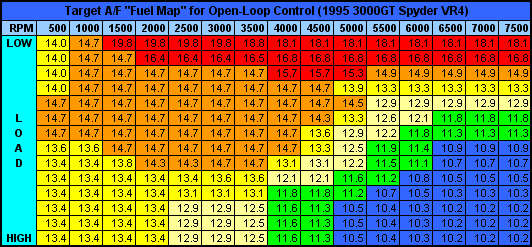
Below is an example "fuel map", courtesy of Matt Jannusch and the DSM-ECU Yahoo! Group, for a 1995 3000GT Spyder VR4. The actual values in the ECU are in the range of 0 to 255, with 128 representing a 14.7 A/F. A map value of 150 represents an A/F of (128/150)*14.7 = 12.544. Notice that the map is not a smooth progression of numbers. The "fuel map" for an engine is produced by systematically varying engine speed and load and then finding the optimal A/F ratio to produce the desired combination of power, fuel economy, low emissions, and knock prevention. The ECU interpolates between values when engine speed and load fall between map sites. Note how rich the ECU is trying to make high-rpm and high-load operation with A/F ratios of 10.2 to 10.3. Better values would be closer to 11.5 if engine knock (detonation) can be controlled. Also notice the values near 14.7. These orange cells indicate the combinations of engine load and RPM where the ECU expects there should be or could be closed-loop operation, but because of perhaps an oxygen sensor malfunction the ECU is in open-loop mode.
Fuel cut
When certain conditions occur, both open-loop and closed-loop controls are ignored and fuel delivery is completely shut off, that is, the ECU does not send the injector activation signals. This is called fuel cut. There are three situations in which this occurs.
The engine speed exceeds 7300 rpm (overrun protection).
The A/N reaches or exceeds the prescribed value (overboost protection).
The throttle plate is closed during engine deceleration above a certain speed (reduces emissions).
Using O2 meters to determine ECU fuel control mode
An O2 meter monitors a factory oxygen (O2) sensor. The O2 sensors simply report to the ECU the oxygen content in the exhaust stream converted to a voltage. The oxygen content (actually, the difference in the partial pressure of oxygen in the exhaust compared to the partial pressure of oxygen in the atmosphere) is directly related to the air-fuel mixture. It is the ECU that controls the air-fuel mixture, not the O2 sensors. At cold engine start-up the O2 meter will briefly read rich (blue lights on a SplitSecond ARM1, pictured below, or voltages above ~0.8) then probably switch to lean (red lights on the ARM1, or voltages below ~0.1) and slowly move toward the rich end (increasing voltages). As the engine warms the lights will start to cycle about once every second or two (green and yellow lights on the ARM1, voltages going back and forth between ~0.1 and ~0.8). This is normal and called closed-loop operation; the ECU is using the O2 sensor voltage in a closed-loop feedback to increase a little then decrease a little the fuel injector pulse width in an attempt to achieve an approximate 14.7:1 mixing ratio. As the engine rpm slowly increase, the cycling rate of the lights (or voltages) will also increase. Compare at idle and at steady 2500 rpm with the car parked. When the car is traveling at constant speed on level ground the voltages/lights should also cycle. If the engine rpm increase rapidly (car stationary) or the car is accelerating, the O2 meter will indicate a rich condition; this is open-loop operation and voltage should stay above ~0.8 volts. When the throttle is closed rapidly, the O2 meter will show lean and maybe no lights or 0 volts because the injectors are being shut off by the ECM (fuel cut). At low-load cruising and light acceleration, the lights should cycle to indicate closed loop operation, similar to that shown below for an ARM1.
Using O2 meters to determine A/F
The 3S ECU uses the factory narrow-band oxygen sensor like a low-high switch for closed-loop fuel control. For open-loop fuel control the ECU ignores the O2 sensors. The reason for this is that the O2 sensor voltage changes very little, and in a non-linear manner, as A/F changes outside the limited range of ~14.55 to ~14.85, that is, the O2 sensor is relatively insensitive to changes in A/F below 14.55 or above 14.85. In addition, O2 voltage in the rich region is dependent on the temperature of the sensor; hotter temperature reduces the output voltage in the rich region by about 0.03 volt per 100ºC. The lean and stoichiometric regions are not affected by temperature to any significance. Our heated sensors only guaranty a minimum temperature. Ideally, an ECU would use a wide-band oxygen sensor to monitor the exhaust stream to achieve the target A/F. Wide-band O2 sensors were not used in the 3000GT and Stealth. Instead, the ECU relies on fuel maps that were developed to achieve various combinations of performance goals concerning emissions, power, and engine safety.
As I mentioned above, when an ASI or MAS converter is installed with larger injectors the ECU will calculate a lower engine load than is really occuring (less airflow than there really is). This means that slightly leaner fuel mixtures may be used at high engine speeds and loads, as well as slightly higher ignition timing advance than what Mitsubishi engineers thought was appropriate (see example timing advance angle map below and example "fuel" map above, and 2-ignitionsystem.htm). This may result in an increased tendency for engine knock, which affects both power (from reduced ignition advance) and engine safety (from increased pressure and wear on engine block components).
Ideally you should install and use wide-band O2 sensors to determine A/F when adjusting the S-AFCII. However, the factory O2 sensors can be helpful, despite their limitations. Look again at the voltage curve above for a typical oxygen sensor. Note that the voltage does change slightly in the rich and lean sections. In fact, at a given temperature the voltage at say an A/F of 12 can be consistent and repeatable (given the same engine operating conditions). The problem is that voltage can be different from sensor to sensor and car to car, and depends on sensor temperature, age and condition. As you adjust the S-AFCII to change A/F for open-loop operation, the O2 voltage will increase as you richen the mixture. While you won't know the real A/F, you can tell that the A/F is getting richer or leaner as you make adjustments. This is helpful. Also, you will find a voltage that works best for your engine to control knock. Note that best knock control can mean an A/F that is richer than for best engine power or torque.
Fuel Trims
The ECU monitors the switching and voltage of the oxygen sensors during closed loop operation and sets values called "fuel trims" that adjust fuel delivery during low, middle, and high (relatively speaking) air flow amounts. These basically do not affect open-loop operation for 1991-1993 models, and do affect somewhat open-loop fuel delivery in 1994-1995 "hybrid" models. For 1996+ models (OBDII) there is a short-term and long-term trim that affects either closed-loop or open-loop operation.
For 1991 to 1993 OBDI models, if our ECUs are programmed similar to the OBDI DSM ECUs, the fuel trims are only used during closed-loop operation (verified in the computer code by the DSM-ECU Yahoo! Group). However, the high trim may be updated during open-loop if Hz is low enough (examination of computer code is not complete at this time). The ranges below are for the 1G DSM MAF. Our 3S MAF (identical to the 2G DSM MAF) may be a bit different (also 4 cyl DSM vs. 6 cyl 3S), but you get the idea: fuel trims are set at low air flow amounts.
Trim goes from low to mid at 106 Hz.
Trim goes from mid to low at 94 Hz.
Trim goes from mid to high at 182 Hz.
Trim goes from high to mid at 170 Hz.
So,
Low Fuel Trim = less than (94-106) Hz,
Mid Fuel Trim = (94-106) to (170-182) Hz,
High Fuel Trim = greater than (170-182) Hz, and
there is also an O2 trim.
For the 1994 to 1995 model "hybrid" ECU, there are still 3 fuel trims. The ranges may be similar to OBDI. And like OBDI, high trim is all flow above a certain value. However, unlike OBDI, high trim is used as a compensating factor in open-loop mode. O2 trim is still there too.
For the 1996 to 1999 model OBDII ECU, from OBDII standards there are two trims: short term and long term. Short Term Trim is equivalent to the OBDI/hybrid O2 Trim and is used only during closed loop. Long Term Trim is persistent, covers all MAF flow rates, and is used as compensation for both closed-loop and open-loop modes.
The "ideal" trim is 100 for the Low, Middle, and High Trims (1991-1995 pre-OBDII models). When the trim is greater than 100 then the ECU is adding fuel because it perceives that the closed loop A/F was on the lean side of "14.7". Adjusting the trim is supposed to return the A/F to "14.7". If the fuel trim is less than 100 then the ECU is subtracting fuel to compensate for a perceived previous rich condition during closed loop operation.
Note that these trim values are not a percent (1991-1995 ECUs), well not directly. According to the DSM-ECU Yahoo! group gurus, each 4 trim points is the same as a 1% change. For example: trim = 96 means the ECU decreased fuel delivery amount by 1%; trim = 81 (or 80) means fuel delivery is decreased by 5%; trim = 110 means fuel delivery increased by 2.5%; trim = 141 (or 140) means fuel delivery increased by 10%. Trim ranges from 81 to 141 (-5% to +10%) on 1991-1993 OBDI models (I think; at least these are the ranges for my 1992 Stealth TT). You can see that Mitsubishi prefers to limit how much the A/F can be leaned in closed-loop mode. As long as the trim is not pegged at one end or the other, you are pretty much OK. If the trim is pegged, then there is a chance the ECU may not be able to keep the closed-loop A/F near "14.7".
INITIAL SETTINGS BEFORE STARTING THE ENGINE
You need to set the following before starting the engine.
Throttle opening setting - These are the Lo and Hi throttle positions that are assigned correction factors for each of the Ne points (rpm values).
Ne points - These are the engine rpm values that will be assigned air correction valuesat Lo and Hi throttle openings.
Initial air correction factors - These are the starting corrections based on fuel injector size.
1. Select/set Lo and Hi throttle opening settings.
You must set a low throttle opening and high throttle opening setting. These are the percent the throttle is open; 0% = closed (but not 0 volts), 100% = wide open (but not 5 volts). Each of these settings will be assigned an air correction factor at each Ne point. Below the Lo value the S-AFCII will use the Lo correction. Above the Hi value the S-AFCII will use the Hi correction. Between Lo and Hi the S-AFCII linearly interpolates between the two corrections. The Hi percent must be great thean the Lo percent.
My philosophy is that the Lo value should be the largest throttle opening such that the ECU is still in closed-loop mode; and the Hi value should be the smallest throttle opening such that the ECU is always in open-loop mode. My reasoning is that below the Lo throttle opening let the ECU do its job of controlling closed-loop mode based on O2 sensor feedback. And above the Hi throttle opening let the ECU do its job of controlling open-loop mode based on its "fuel maps". This also makes it simpler to set the correction factors at the Lo and Hi openings for the Ne points; Lo openings are to adjust closed-loop operation up to a certain rpm (~4500) and HI openings are to adjust open-loop operation. Closed-loop and open-loop fuel control modes were discussed above.
You can determine these throttle openings by datalogging over a wide variety of driving situations (which you should have done before installing the S-AFCII). For my car with an ARC2-GP installed and 550 cc/min injectors and an adjusted throttle position sensor (TPS) the ECU was always in closed-loop mode below about TPS 1.25 volts (25% of 5 volts) and always in open-loop mode above about TPS 2 volts (40% of 5 volts). The TPS voltages (or percents) can be different for your car. A datalogger will tell you what the closed position and wide open voltages are (or you can convert from the TPS percent). The closed and WOT voltages turn into the S-AFCII 0% (closed) and 100% (wide-open) throttle opening values. You will have to make the conversion between the two systems. I set my S-AFCII Lo and Hi to 25% and 40%, respectively. But remember, the throttle position and therefore airflow vlaues are already influenced by the ARC2-GP and larger injectors I have installed. You must datalog and discover these throttle openings for your car, first with stock injectors and next after larger injectors are installed.
If you cannot datalog, you might try using 25% for Lo and 50% for Hi. After the S-AFCII is working you can observe the TPS percentage on the S-AFCII monitor and the functioning of O2 meters to adjust these throttle openings.
2. Select/set the Ne (rpm) points.
The S-AFCII start-up Ne points go from 1000 rpm to 7600 rpm in 600 rpm steps (12 points). Our standard idle speed is about 700 rpm and redline is 7300 rpm. So I lowered all the points by 200, keeping the 600 rpm step. The lowest rpm allowed is 800; the highest is 9800. Steps can be as small as 200 rpm and do not have to be the same between all Ne points. At engine rpm below the first Ne point, the S-AFCII uses the corrections assigned to the first Ne point. At engine rpm above the last Ne point, the S-AFCII uses the corrections assigned to the last Ne point. At engine speeds between the Ne points the S-AFCII linearly interpolates.
3. Select/set initial air correction factors based on injector size.
The most important function of the S-AFCII is to adjust the airflow signal. For our engines, which use a Karman-style mass air sensor, the air volume flow is reported in Hz, a square-wave voltage signal repeated many times per second. Air temperature and barometric pressure are also measured by the MAS and used by the ECU to determine air mass flow. A zero setting (0% correction factor) does not change the signal. A positive setting (greater than 0% correction factor) increases the airflow signal, essentially richening the mixture. A negative setting (less than 0% correction factor) decreases the airflow signal, essentially leaning out the mixture.
If you have the factory fuel injectors installed, or are already using a MAS conversion device like the ARC2-GP, MAF-T, or PRO-M, then start with all correction factors, Lo and Hi at all Ne points, at zero. I recommend not installing the S-AFCII at the same time as a MAS conversion. Get the MAS conversion working first (if you want or need to install one) then add the S-AFCII if needed.
After you install larger injectors, and are not using a MAS converter or are using a MAS converter but have it set at "neutral", use the formula below to determine an initial correction factor for all corrections, Lo and Hi at all Ne points. Thanks and credit go to Brian Geddes for this formula.
The principle with this adjustment is that since fuel injectors are installed that flow more than the factory injectors, we must fool the ECU into thinking we are still using the factory injectors. We do this by lowering the airflow signal rate (Hz). The ECU "sees" less air flowing (than there really is) and so it reduces the fuel injector activation time (reported by dataloggers as injector pulse width, IPW, in milliseconds). Since larger injectors are installed, that is, since larger injectors squirt more fuel per millisecond than factory injectors, it all evens out. One consequence of this system is that the engine calculates less engine load (a lower A/N) than there really is. This can result in (1) more timing advance, (2) leaner target A/F during open-loop fuel control, and (3) higher airflow (higher boost) before overboost-protection fuel cut occurs. Use your datalogger during WOT runs to compare timing advance with factory injectors installed and then after installing larger injectors. Note that some dataloggers show a timing advance that is 10º higher than the ECU is using. Be sure you are in "3S" mode if available and not "DSM" mode. Also, the ECU does not include the basic ignition timing advance (usually 5-7º) in the value it reports, but some loggers might add this value in. As far as overboost-protection fuel cut, I have not heard of anyone reporting this type of fuel cut with 550 cc/min or larger injectors installed. You can see a comparison of two datalogs recorded with the ARC2-GP installed (no S-AFCII) with 360 and and 550 injectors at my web page 2-tmo1.htm. The TMO datalogger reports timing advance in "DSM" mode so values are 10º too high.
ADJUSTING THE S-AFCII WITH THE ENGINE RUNNING
Up to now, you can make all adjustment and settings in the S-AFCII with the car parked (and engine off). These final adjustments to the airflow correction factors will require that the car be driven. I cannot stress enough to make these adjustments in the safest manner possible so that you or others are not harmed and so that your engine is not harmed. If possible, have somebody ride with you to make adjustments while looking at the datalogger and/or gauges or to drive the car while you make the adjustments. If you are by yourself, try to to use a private street or one with very little traffic (try early Sunday mornings for public roads). You can also record a datalog while driving, then review it after parking the car and make necessary adjustments to the S-AFCII.
At this point my experience adjusting the S-AFCII will probably be different than what yours will be. I already have installed a MAS conversion kit (ARC2-GP) that is adjusted properly so that the car runs well. My adjustments of the S-AFCII will be to fine tune the A/F and closed-loop control to make the engine performance even better. If you are using the factory MAS, your adjustments will be more complicated. Nevertheless, the instructions and tips below should be useful because I had to use the same general procedure with my ARC2-GP.
4. Start engine (car parked) and adjust air correction factors for the Lo throttle opening at the Ne points.
OK, you should be ready to start the engine and adjust for closed-loop mode. Put the S-AFCII into "Setting" mode. Only the Lo throttle settings for Ne points less than 5000 rpm will be adjusted in this step. I suggest leaving the Lo throttle settings for all Ne points at and above 5000 rpm at settings established in step 3 above. The ECU should never be using closed loop mode above 5000 rpm.
If the factory injectors are installed, the correction factors at Lo and Hi settings at all Ne points should be zero. Otherwise they should be set as explained above. The engine should start and warm up as it normally does. If the engine will not start then check that (1) the initial setup was performed correctly, (2) all corrections factors are set correctly for the size injectors installed, and (3) that the electrical installation of the S-AFCII is correct (no broken wires, no electrical shorts, correct ECU and S-AFCII wires connected, etc.). If you have flooded the engine, remove the front 3 spark plugs for about 15 minutes, dry them off and re-install, lean-out the lowest Ne point Lo setting, and try starting the engine again.
Once the engine is at warm idle (~700-750 rpm), observe the O2 meters or O2 sensor voltages on the datalogger. The O2 sensor voltages should be cycling back and forth between ~0.1 and ~0.8 volts, indicating closed-loop fuel control (see sample datalogs below). If not, adjust the Lo throttle setting for your lowest Ne point until O2 voltages are cycling. Make changes slowly, one or two 1% steps at a time. If the voltage is staying near 0.0 then richen the mixture (increase correction). If the voltage is staying above ~0.8 then lean out the mixture (decrease correction). Wait a minute maybe to see the effect of the change.
After the ECU is operating in closed-loop mode at warm idle, with the car parked, slowly raise the engine rpm to each successive Ne point and hold it there. Adjust the Lo throttle opening if necessary so that the ECU remains in closed-loop mode. Stop at the highest Ne that is less than 5000 rpm.
I don't pay too much attention to the fuel trims. For my last emissions test all three fuel trims were at a minimum (81 for my 1992 TT), supposedly meaning the ECU was reducing fuel injector activation times in response to what it perceives as a mixture that is too rich, and the engine passed just fine. As long as the ECU is in closed-loop mode (indicated by the cycling O2 voltages) you know the A/F is within a very narrow range of 14.7. You can try to keep the fuel trims close to 100% but it is not required. When you disconnect the battery negative terminal for more than about 10-15 seconds, the ECU is deprived of power and resets all three fuel trims (Low, Middle, and High) to 100% (OBDI). At idle with the car parked, you may be able to adjust the lowest-Ne airflow correction factors and see the Low Fuel Trim change in response. On my 1992 Stealth TT, the Low Fuel Trim will not change if the car is moving. Also, the Low Fuel Trim will go to 140% with the air conditioning on and go to 81% with the AC off. I have no explanation for this.
As discussed above, in closed loop mode the A/F will be in the range of ~14.55 to ~14.85. You can use the airflow correction to adjust the closed-loop A/F within this range, that is, very slighly richer or leaner than exactly "14.7". This may be important to you at emissions testing time. For my car, if the O2 sensors are cycling in the leaner range of 14.55-14.85 the engine will miss when held at about 2000-2500 rpm (spark misfires were verified with a timing light), causing excess HC emissions from the unburnt fuel. Adjusting the closed-loop A/F to the richer end of 14.55-14.85 will cause the engine to run smoother and cleaner.
5. Drive car with low engine load (ECU closed-loop mode) and adjust air correction factors for the Lo throttle opening at the Ne points.
The ECU should be using closed-loop fuel control when the engine load is low and rpm is less than 4500 to 5000. The engine is under low load (low airflow rates and low throttle openings) during idle and when the car is travelling on level ground at a constant speed or very slightly accelerating. As you cruise in different gears and at different constant vehicle speeds (so that the engine is at different but steady rpm), adjust the appropriate Ne point Lo settings so that the ECU is in closed-loop mode (O2 voltages cycling). Occasionally give the car a little gas to accelerate some and you should see voltages stop cycling and stay above 0.8. Voltage may go above 0.9 if you accelerate quickly. If you let off on the throttle compeletely to slow down you may see voltages go to zero (fuel cut).
However, the point here is to get the Lo throttle settings for Ne points less than 4500-5000 rpm adjusted correctly. Drive the car slowly (20-45 mph) at a constant speed and if possible at constant moderate highways speeds (50-70 mph). In both cases the ECU should be in closed-loop mode. Note that in higher gears you may effectively increase engine load due to reduced mechanical advantage from the transmission. If the ECU is not in closed-loop mode, adjust the Lo settings for the various Ne points covering the engine speeds used until the ECU is in closed-loop mode. Remember, the Lo throttle position setting is just above the value you found that the ECU will always use closed-loop mode with factory fuel injectors.
6. Drive car with higher engine load (ECU open-loop mode) and adjust air correction factors for the Hi throttle opening at the Ne points.
At this point you need to use the O2 and EGT readings and knock counts to perform the final adjustments to the airflow correction factors. The goals are (1) to be sure the ECU is using closed-loop fuel control when it should be, and (2) when the ECU is in open-loop mode that the air-fuel ratio (A/F) is at the appropriate richness. I recommend keeping notes about the different engine operating conditions, boost levels, weather conditions, etc. and the settings you use on the S-AFCII.
If you have installed one or two wide-band O2 sensors, then use the displayed A/F to precisely adjust the S-AFCII. Closed-loop mode (idle and cruising) should show an A/F near 14.7 +/- 0.2. During open-loop cruising strive for an A/F in the 12 to 13.5 range. During WOT acceleration, try to keep A/F between 11.5 and 12. Be warned though, knock may become a problem (counts over 7 to 9) at this A/F, and you may have to run richer mixtures (lower A/F) to cool the intake charge and reduce knock. A better way to reduce knock would be to try and keep A/F near 11.5-12 for better torque and power, and use water/alcohol injection or propane injection to cool the intake charge.
Now it is time to adjust the correction factors for the Hi throttle position settings for all the Ne points. These represent moderate to high engine loads, which occur during high-speed cruising, uphill travel, and medium to WOT acceleration. The engine will use open-loop mode for these situations, and, if you use my suggestion, the Hi throttle position will be at the lowest throttle opening such that the ECU will always be in open-loop mode. For throttle openings between the Lo and Hi settings, the S-AFCII will interpolate between the two airflow correction factors, providing corrections when transitioning between closed- and open-loop modes.
In open-loop mode the ECU is using its fuel maps, which represent target A/F ratios, to adjust the basic injector activation time. The airflow correction factors we set for the Hi settings for the Ne points will be (1) to compensate for larger injectors, (2) to be sure the ECU is in open-loop mode when it should be, and (3) to provide a little richer or leaner mixture than the factory ECU programmers may have built in. Here is where wideband O2 sensors are really needed. If you don't have these (I don't at this time, September 2004) then you'll have to make do with the factory narrowband O2 sensors plus any EGT gauges and the knock count the datalogger provides (1991-1995 models only, no knock information is provided by OBDII loggers).
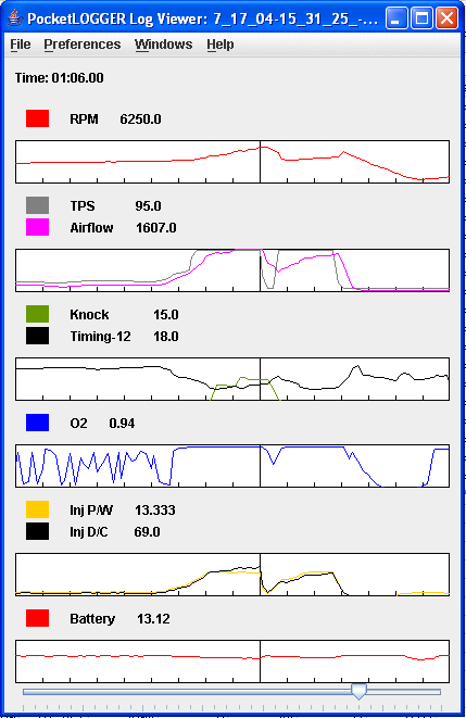
Some owners suggest you pay attention to timing values, mostly because they think timing retards when knock is present. My extensive experience logging my 1992 Stealth TT and looking at the logs of others indicates that timing retards a little or moderately when knock increases. When knock is constant, even at a high count, the ECU can hold timing constant and even increase timing. Timing advance or retard, as shown on the datalogger, is not a reliable way to estimate knock. For example, look at the recent log below. Look at how timing increases overall while knock is occuring. Only when knock abruptly jumps to ~16 counts does timing retard a degree or two. When knock stays at 15 counts timing again begins to increase. The timing values are corrected to "3S" values by subtracting 10 from the values stored in the datalog. I incorrectly subtracted 12º in these figures. Until I fix the figures, please add 2º to the values shown.
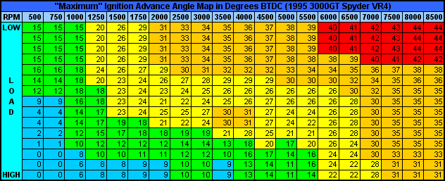
I am not suggesting you ignore ignition timing advance. Just saying it is not a reliable way to tell if knock is occuring. Below is an example "timing map", courtesy of Matt Jannusch and the DSM-ECU Yahoo! Group, for a 1995 3000GT Spyder VR4. In general, timing advance increases with engine speed and decreases with engine load. Because the time to initiate combustion after a spark is fixed for a given load, ignition must start sooner at higher engine speeds (timing is advanced more). However, at a given engine speed as the load increases, meaning as the air-fuel charge density increases, combustion proceeds faster after ignition and so ignition must be delayed (less advanced) a little. Notice that the map is not a smooth progression of numbers. The timing map for an engine is produced by systematically varying engine speed and load and then finding the optimal advance to produce the desired combination of power, fuel economy, low emissions, and knock prevention. The ECU interpolates between values when engine speed and load fall between map sites. Note that correction values for coolant temperature, barometric pressure, intake air temperature, and knock count are added to the value extracted from the advance angle map.
As I mentioned earlier, when using an ASI or MAS converter with larger injectors, the ECU calculates less load and so timing values can be higher than the Mitsubishi engineers planned for. This is especially true at medium to high loads below about 5500-6000 rpm. On the other hand, look at all the 26º values in the 6000 rpm column, the 28º values in the 6500 rpm column, and the 30º values in the 7000 rpm column. Reducing medium-high load by 25-35% will have little effect on timing advance in these upper rpm ranges. You can determine the aproximate increase in timing do to reduced perceived load by the ECU using the correction factors shown above for the different sized injectors. For example, for 550 cc/min injectors expect a 5 "row" change in load (multiply the 15 load rows by 35%).
Engine rpm will change too rapidly during WOT pulls to make adjustments to the Hi throttle setting for the Ne points in "real time". So, record datalogs during partial and WOT acceleration in each gear. Include the following in the datalog: rpm, airflow, TPS, IPW, IDC (injector duty cycle) if available, timing, knock, rear O2, and front O2 if available. If your datalogger can pass through EGT readings, and you are setup for this, also record these measurements. If you cannot log EGT then try to pay attention to the peak values on the gauge.
Look at O2 voltages and knock counts in the datalogs. Many owners find that A/F is not rich enough to quell knock when O2 sensor voltage is below 0.88 to 0.90 at WOT, depending on EGT, octane rating of the gasoline, boost levels, and if water/alcohol injection is used. Ideally, knock counts should be zero. However, counts up to 7 to 9 often do not pull timing, meaning that Mitsubishi engineers thought this could be a "safe" level.
The EGT suggests whether the air-fuel ratio is relatively rich or lean. This information is most useful during wide open throttle engine operation. At WOT, values between 850ºC (1562ºF) and 900ºC (1652ºF) are often considered ideal; temperatures below 800ºC (1472ºF) are considered too rich; temperatures above 925ºC (1697ºF) and approaching 1000ºC (1832ºF) are considered dangerously lean and can result in excessive engine detonation (knock) and possibly burnt or melted components (valves, spark plugs, pistons, rings). Note that the placement of the EGT probe affects the measurement (the farther the probe is from the head exhaust port the cooler the temperature can be) as does the amount of ignition timing advance (more advance can mean cooler temperatures).
Review your datalogs, notes, and gauge readings and make adjustments to the Hi throttle setting of the NE points as needed. This can be an iterative process and may take some time.
Some sample datalogs
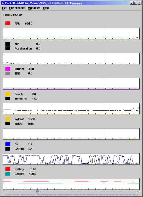
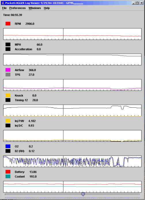
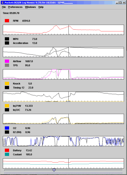
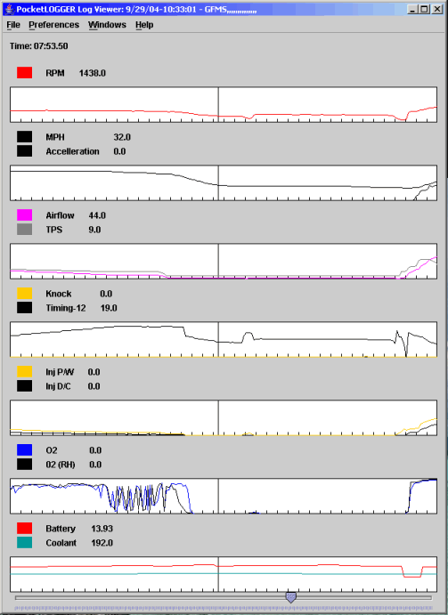
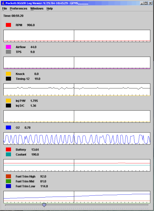
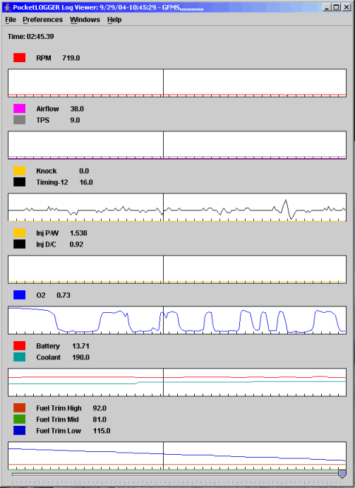
Below are some "snapshots" from datalogs recorded that mixed city and highway driving and one at warm idle. I used the PocketLOGGER Log Viewer (a free Java program). The first version is available at (misc/plviewer.zip) and the second version at (misc/plviewer2.zip). Each version has their own peculiarities. I tend to use the first version. The second version has a neat "scatter-graph" tool. I like to group the parameters as shown. The vehicle speed (in mph) and acceleration (not sure of units) are provided by the Scanmaster 3 as substitutions for the ISC and Accel Enrichment signals, respectively. The PL Log Viewer will use any CSV file that is formatted correctly. To convert CSV files from the other dataloggers, look at CSV files produced by the PockeLOGGER Converter program (misc/pl2csv.zip) and pay special attention to formatting of values in the time column. The Log Viewer will use the column titles you provide (yes, I realize I misspelled acceleration in the CSV file). Note that the Airflow (in Hz) is that seen by the ECU, and so it is the signal after being modified by the ARC2-GP and S-AFCII. Also, I present the wrong correction to the PocketLOGGER timing advance values. I should have subtracted 10º rather than 12º. I'll correct these figures when I get a chance. Until then, add 2º to the timing advance values shown.
The first pair of logs show closed-loop mode at warm idle and cruising at highway speeds (air conditioning and headlights are off). The parameters to look at for adjusting the S-AFCII are engine speed (rpm) and TPS (%). The TPS percent shown here is a fraction of 5 volts. For my engine, 9% is closed throttle and would indicate 0% on the S-AFCII. WOT TPS would be 95% on my datalogs and would be 100% on the S-AFCII. The IPW (in milliseconds) is dependent on the fuel injectors installed and the adjustment of the ARC2-GP and S-AFCII. IDC (in percent) is calculated by the Log Viewer as RPM times IPW divided by 1200. Non-S-AFCII-related features are the battery voltage (these seem typical for warm idle as well as cruising), coolant temperature (ambient temperature was in the mid 70's ºF), and the O2 readings (voltages). Note the O2 voltages are cycling at a rate of one cycle about every two seconds at idle (~700 rpm), but at a rate 1 to 2 cycles per second at ~3000 rpm. The cycling values indicate the closed-loop ECU mode.
The next image shows open-loop fuel control during wide-open throttle acceleration with boost at 15.6 psi (1.1 kg/cm2) to redline (air conditioning and headlights are off). S-AFCII-adjusting parameters to look at are RPM, Knock, and O2 values. Note that timing is not retarded at a knock count of 5. Generally, timing advance is not retarded until the knock count reaches 7 to 9, which must be what Mitsubishi engineers considered an acceptable level. Oxygen sensor voltages are both the same and are at relatively constant values above 0.8, indicating the open-loop ECU mode. For my car 0.96 seems to be the magic voltage for tolerable knock counts given these engine and environmental conditions. I don't know what A/F this value represents. For your engine, O2 voltages may be greater or less than what works for my engine. Other features to note are the reduced battery voltage at WOT (indicating possibly less voltage to the ignition system and fuel pump), lower coolant temperature at WOT (a good thing) because of the greater airflow across the radiator, and an acceptable IDC of about 73 percent (less than 80-85% at WOT is usually good). Timing advance at 24º (22º shown) seems a bit low to me, but I believe the value is correct because the 18º (16º shown) recorded at idle matches the timing light and DRB II values. Many owners hypothesize that larger injectors will increase timing too much because the ASI reduces the airflow (and engine load) perceived by the ECU. This datalog with 550 cc/min injectors does not indicate such a problem.
The datalog below shows fuel cut during deceleration. Note the zero values for IPW and O2.
These last two images are not presented to help adjusting the S-AFCII but to show how the low fuel trim changes with the air conditioning on and off with the car parked and at warm idle. This log was recorded immediately after the above log. With the AC on, RPM, Airflow, Timing, and IPW are higher. The O2 sensor is cycling at a smooth and constant rate. Also, the LFT value is steadily increasing on its way to 141. With the AC off and the LFT decreasing on its way down to 81, the battery voltage increases a little and the O2 voltages and timing advance corrections vary less smoothly and less regularly.
Maximum power vs. safe power, and ways to reduce knock
Adjusting the S-AFCII for power will always be a compromise between maximum power (highest output) and safe power (engine longevity). Maximum power will usually happen near an A/F of about 12 to 12.5. However, on street gas an A/F of 12.5 at high boost usually causes lots of engine knock (detonation) - bad for "safe" power. For me, I tune to reduce knock because knock can destroy the bottom end of the engine; and the maximum engine output won't do me any good if the engine is torn apart for a rebuild. The following steps can be used to reduce knock.
Reduce boost level (at least until you implement one or more of the following).
Use higher-octane rated gasoline.
Richen the air-fuel mixture (lower the A/F), but note that if A/F gets too low (I have read around 9 to 9.5), these rich mixtures may actually promote knock.
Use spark plugs that are 1 or 2 or more ranges cooler (see 2-sparkplugtech.htm).
Cool the intake charge with water injection, alcohol injection, or propane injection.
Retard timing using an external device, such as the A'PEXi ITC ("global", fulltime timing retard) or the J&S Electronics Safeguard (individual cylinder timing retard only when the engine knocks).
Clean the combustion chambers (water/alcohol injection can take care of this) to remove carbon buildup and potential hotspots.
Reduce engine coolant temperature with a goal of no more than 195º to 200ºF (not sure how this can be achieved).
Use forged pistons (crowns run cooler than cast piston crowns).
Switch to a standalone engine management system so you have better control of ignition timing and fuel mixtures.
7. While driving car over the next few days make fine tuning adjustments as necessary.
Most of us are pretty happy just to have the engine running well after adding larger injectors and an airflow signal interceptor or MAS conversion. However, as you become more familiar with your engine and ECU you may want to continue "fine tuning" the S-AFC to tweak engine performance or to compensate for other modifications, such as cooler spark plugs or water injection. Fine-tuning includes the adjustment procedures mentioned above and the following.
Adjusting the Lo and Hi throttle settings for the Ne points. Specifically, you may want to change the settings for the mid to high rpm Ne points to reduce or eliminate knock.
The correction factor at the Lo throttle setting for 4500-5000 rpm and above Ne points should be constant and at the same factor used for the Ne point just below this range.
Resetting the ECU (unplug battery negative cable for 10-15 seconds) if knock has been occuring extensively and the ECU has switched to a lower timing advance map.
You may also want to establish two patterns of settings, say one for the street and one for the drag srip. For most of us, the added performance of larger injectors and turbos more than balances the effort to install and adjust an ASI or MAS converter.