The Ignition System
in the DOHC Mitsubishi 3000GT and Dodge Stealth

by Jeff Lucius

   Topics
         
Introduction
Ignition Timing Control System
Power Transistor Unit
Ignition Coils
Ignition Wires
Spark Plugs
Summary
References

Introduction

This technical note describes the ignition system on the DOHC-engine models of the Mitsubishi 3000GT and the Dodge Stealth. The 6G72, DOHC, 24-valve, 2.972-liter, V6 engine uses a distributorless, inductive-discharge ignition system that is electronically controlled. The ignition system's purpose is to deliver sufficient energy to the spark plug at the correct time during the compression stroke. The engine control unit (ECU) determines the operating condition of the engine from the sensor input listed below to determine which cylinder to fire and at what time.
  • Air flow sensor (AFS)
  • Intake air temperature (IAT) sensor
  • Barometric pressure sensor
  • Engine coolant temperature sensor
  • Idle position switch (IPS)
  • Top dead center (TDC) sensor
  • Crank angle sensor (CAS)
  • Vehicle speed sensor
  • Inhibitor switch (automatic transaxle only)
  • Ignition switch (ST)
  • Detonation sensor

The ignition system consists of the sensors listed above, the ECU, a power transistor unit, three ignition coils, six ignition wires, and six spark plugs. The ECU activates a power transistor to turn the primary current of an ignition coil off and on. Each ignition coil fires a pair of spark plugs simultaneously.

Ignition control system schematic
The cylinders are arranged and numbered as shown below. Because each piston begins its combustion stroke 120º before the next numerically successive cylinder, there are three "pairs" of cylinders, 1-4, 2-5, and 3-6. Each cylinder pair moves up and down together and is at top dead center (TDC) at the same time. The firing order is 1-2-3-4-5-6.
Mitsubishi 6G72 cylinder numbers
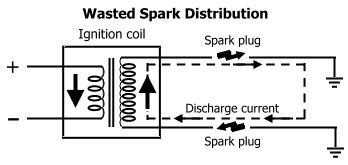
Paired cylinders have pistons at the same relative position, such as both at TDC. However, the paired cylinders are 360º out of phase, such that one is in the exhaust stroke while the other is in the compression stroke. Spark plugs are fired simultaneously in paired cylinders, during the compression stroke for one cylinder and during the exhaust stroke for the other cylinder. The spark during the exhaust stroke is wasted because the basically inert exhaust gas cannot combust. This is called a wasted spark ignition system. An interesting consequence of this system is that the center electrode is positively charged for one spark plug of the pair but is negatively charged for the other spark plug.

Wasted spark distribution

Ignition Timing Control System

Using signals from various sensors, the engine control unit determines which cylinder is to fire and at what time. This section describes the ECU functions and controls that are part of the ignition system.

Ignition Timing Control Functions
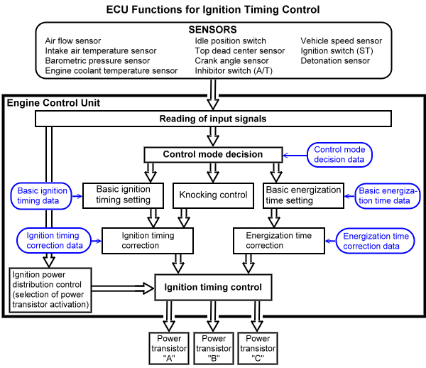
The block diagram below shows the ECU functions for ignition timing control. In order to determine optimum ignition timing, the ECU extracts values from a basic ignition timing advance angle map and then adds corrections for engine operating conditions and the energization time. The details of these controls are discussed in the next sections.

Ignition timing control functions

Ignition Power Distribution Control
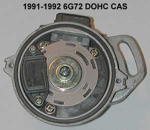
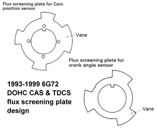
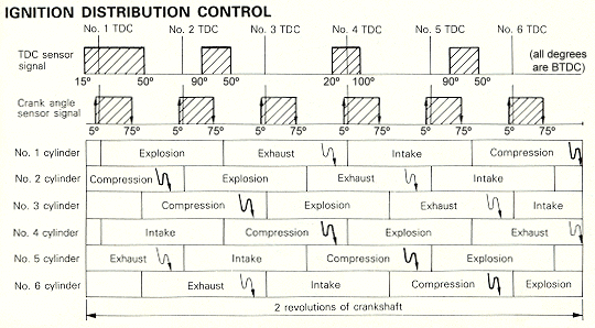
The cylinder pair to be ignited is determined by the ECU from the crank angle sensor (CAS) and top dead center sensor (TDCS; also called the cam position sensor, CPS) signals. The design of the CAS and TDCS changed in 1993. For 1991-1992 DOHC models the CAS and TDCS are both in the same housing located on the rear end of the left-bank intake camshaft. Beginning with the 1993 models (June 1, 1992 production date) and continuing till the end of production, the CAS and TDCS were separated and moved to in front of the engine. The 1991-1992 CAS uses two photodiode LEDs and slots cut into a single plate to produce voltage pulses as light passes through the slots, and can be adjusted to set basic ignition timing. The 1993+ sensors each use a flux screening plate and a Hall-effect switch to produce voltage pulses as the vanes interupt the magnetic flux, and cannot be adjusted. As shown in the figures below and for all model years, the CAS outputs 3 pulses for every rotation of the crankshaft and the TDCS outputs 2 pulses for every crankshaft rotation (the camshaft rotates at half the speed of the crankshaft). The TDCS signal for cylinder 1 TDC is longer than the other 3 signals. If you are interested in using a 1991-1992 CAS with a 1993+ ECU, or a 1993+ CAS and TDCS with a 1991-1992 ECU, please read my web page 2-cas_conversion.htm.

1991-1992 6G72 DOHC CAS slotted disk    1993-1999 6G72 DOHC CAS & TDCS screening plate design

The ECU uses three unique combinations of the CAS and TDCS signals being high (voltage present) and low (no voltage) to determine which cylinder pair should fire. Use the figure below to help interpret the explanations that follow.

If the TDCS signal is high when the CAS goes from low to high, the ECU knows that cylinders 2 and 5 are in either the compression or exhaust stroke. When the CAS then goes from high to low, the ECU uses this as a reference to turn power transistor "B" off to produce sparks in cylinders 2 and 5. If the TDCS is still high at this time the ECU also knows that cylinder 1 was near TDC and is currently on the combustion stroke, and that it was cylinder 2 that was on the compression stroke.

If the TDCS signal is low when the CAS goes from low to high, the ECU waits until the CAS signal goes from high to low to determine which of the other two cylinder pairs should be fired. When the CAS signal goes from high to low and the TDCS is high, then cylinders 3 and 6 are in either the compression or exhaust stroke. If instead the TDCS is low, then cylinders 1 and 4 are in either the compression or exhaust stroke. In each case, the ECU uses this (the CAS signal going from high top low) as a reference to turn the appropriate power transistor off ("A" for cylinders 1 and 4 or "C" for cylinders 3 and 6) to produce sparks in the cylinder pair.

Ignition distribution control

Ignition Timing Control
The ECU determines the time for one engine revolution using three pulses from the CAS signal. The end of the CAS pulse for cylinder 1 is used as the timing reference for cylinder 2. The end of the CAS pulse for cylinder 2 is used as the timing reference for cylinder 3, and so forth. The CAS pulse goes from high to low at 75º BTDC for the next numerically higher cylinder. Using this reference signal and the ignition advance angle calculated as shown in the next sections, the ECU turns off the primary current in the coil to produce a spark in the paired cylinders.

Ignition Advance Angle Control
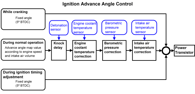
The ignition advance angle (in degrees BTDC) is fixed during engine cranking and during adjustment of basic ignition timing advance. During normal engine operation the ECU first refers to a basic ignition advance angle map stored in memory. This map stores the advance angle for all engine speeds and loads. The load is based on intake air volume and not throttle position. The ECU then applies corrections to the map value based on engine conditions.

Ignition advance angle controlcontrol

Basic Ignition Advance Angle Map
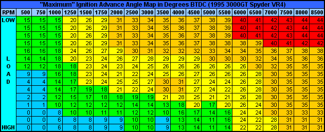
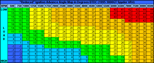
Actual basic ignition advance angle maps (maximum and reduced) for a 1995 Mitusbishi 3000GT VR4 Spyder 6G72 turbocharged engine are shown below (thanks go to Matt Jannusch, Jeff Oberholtzer, and others on the dsm-ecu Yahoo! group for these data). The ECU has a different part number for turbo and non-turbo 6G72 engines. This might mean the ignition maps are also different. In general, timing advance increases with engine speed and decreases with engine load. Because the time to initiate combustion after a spark is fixed for a given load, ignition must start sooner at higher engine speeds (timing is advance more). However, at a given engine speed as the load increases, meaning as the air-fuel charge density increases, combustion proceeds faster after ignition and so ignition must be delayed (less advanced) a little. Notice that the map is not a smooth progression of numbers. The timing map for an engine is produced by systematically varying engine speed and load and then finding the optimal advance to produce the desired combination of power, fuel economy, low emissions, and knock prevention. The ECU interpolates between values when engine speed and load fall between map sites. Correction values are added to the value extracted from the advance angle map. When the ECU is reset (power removed for 15 seconds or longer), the maximum advance angle map values are utilized.

Maximum timing map

Reduced timing map

Knock Delay
The ECU monitors the detonation sensor and processes the voltage information into a measurement called "knock counts". Knock counts are reported to dataloggers for the OBDI models (1991-1993) and for 1994-1995 models. For OBDII models (1996+) knock detection is not reported according to the OBDII protocol. When the ECU detects knock above 8 counts (18.75% of 43) and engine load is above the third "load row", it starts to retard timing. If the knock count increases, the ECU continues to reduce timing advance up to a maximum of 12 to 15 crank-angle degrees. If knock counts reduce or remain constant, the ECU can advance timing. The number of degrees the ECU increases or decreases the "knock delay" is based on what is called the "octane value" (the long-term timing advance trim) and another look-up table called the "delay map". Below a knock count of 3 the octane value is increased toward its maximum value, leading to less knock delay (more timing advance). If the knock count is above 5 the octane value is decreased toward its minimum value, leading to more knock delay (more timing retard). In addition, if the octane value falls below 2/3, the ECU reduces boost. There is a fixed value in the ECU programming controlling how fast (step size) the octane value is increased or decreased. The octane value is reset to its maximum (no knock delay) when the ECU is reset (power removed for 15 seconds or so).

Engine Coolant Temperature Correction
The ECU monitors the engine coolant temperature sensor and advances timing below a specific temperature. Timing is retarded at high temperatures. The table below is for DSM cars (thanks go to Dave Womer and Carl Morris on the dsm-ecu Yahoo! email group), but may be similar for 3S cars.

Engine Coolant Temperature Correction
ºF ºC Timing Change (º)
224 106.67 -2
206 96.67 -1
176 80.00 0
125 51.67 0
95 35.00 0
69 20.56 0
46 7.78 +4
19 -7.22 +8
-3 -19.44 +11

Barometric Pressure Correction
The ECU monitors the barometric pressure sensor in the mass airflow sensor (MAS). When the air pressure is low, that is at higher altitudes, ignition timing is advanced. The dsm-ecu Yahoo! email group has not found a table that performs a separate correction. The barometric pressure affects ignition timing by being included in the "air density" calculation by the ECU, which along with air volume flow and air temperature, in part, determines engine "load". Less-dense air-fuel mixtures (higher altitudes) combust slower than denser mixtures (lower altitudes) and so ignition must start earlier (timing is advanced). Though manuals state that the ignition timing advance correction is from 5º to 15º at higher altitudes, I have not seen this yet in the datalogs of my 1992 Stealth TT (I am at about 5600' ASL). Todd Day (dsm-ecu Yahoo! email group) notes that above 7500' ASL the closed loop feedback loop is tweaked, and that altitude contributes to the ECU's decision to purge the charcoal cannister and to check the EGR system for failure.

Intake Air Temperature Correction
The ECU monitors the intake air temperature sensor in the MAS. When the air temperature is low, for example in cold weather, ignition timing is delayed. Colder air means denser air-fuel mixtures, which both combust faster and can be more prone to knock, and so ignition must be delayed. When the air temperature is high the ignition is also delayed because hotter air-fuel mixtures are more prone to knock. The table below is for DSM cars (thanks go to Dave Womer and Carl Morris on the dsm-ecu Yahoo! email group), but may be similar for 3S cars.

Intake Air Temperature Correction
ºF ºC Timing Change (º)
185 85.00 -3
133 56.11 -1
100 37.78 0
73 22.78 0
48 8.89 0
19 -7.22 -1
-14 -25.56 -2

Energization Time Control
The ECU controls the ignition coil primary current to achieve and then maintain a value of 6 amps. Using mapped values in memory, the ECU lengthens the energization time when the battery voltage is lower, and shortens the energization time when the battery voltage is higher. However, the ECU will not extend the energization time longer than 75% of the ignition interval. Each coil fires once every engine revolution and so the ignition interval is the time it takes for the engine to revolve once. Energization time is about 4 ms. This value must be converted to crank degrees using the engine speed. When the engine is cranking, the ECU energizes the ignition coil in synchronization with the crank angle sensor signal, that is, the timing advance is a fixed value of 5º BTDC.

Idle Stabilization Control
Though I did not see it mentioned in the Technical Manuals, our ECU utilizes small changes in ignition advance to assist in idle speed stabilization. This can be observed on datalogs and with a timing light. When idle speed is below the target speed the ignition timing advance is increased. When idle speed is above the target speed the ignition timing advance is decreased. Timing advance usually only varies by 1 or 2 degrees. At the same time, the ECU is also using the idle speed control servo to control air flow around the closed throttle plate. The combination of these two controls produces a slightly varying engine speed as the ECU constantly tries to maintain the target speed.

Control During Basic Ignition Timing Adjustment
The ECU is placed into "basic ignition timing" mode when the ignition timing adjustment terminal (located in the right rear corner of the engine bay near the battery; see 2-checkconns.htm) is grounded (to the engine or frame). Idle stabilization control and all ignition timing advance angle control are stopped (that is the ignition timing advance angle is set to 0). The mechanical ignition timing advance that remains is called the basic ignition timing advance. This value is 5º BTDC +/- 2º for 1991-1992 models or 5º BTDC +/- 3º for 1993+ models. For 1991-1992 models, the CAS/TDCS can be adjusted to change the basic ignition timing advance (see 2-ignition-timing.htm). For 1993+ models the basic ignition timing advance is not adjustable. Actual ignition timing at warm idle, when the adjustment terminal is not grounded, should be about 15º BTDC +/- 7º (all years).

Power Transistor Unit

For our DOHC 6G72-engined Mitsubishi 3000GT and Dodge Stealth cars the engine control unit provides both dwell control (to generate sufficient energy) and timing control (crankshaft and camshaft position information goes directly to the ECU), relieving the power transistor unit (PTU) of these tasks. The PTU, which can also be called an ignition module or igniter, has only two basic functions to perform: (1) to provide switches, controlled by the ECU, to supply then remove current to each of the three ignition coil primary circuits, and (2) to provide a tachometer signal every time a spark plug fires, which is every 120 crankshaft degrees. In contrast, for example, Toyota often incorporates dwell, timing control, and spark distribution in their igniter units.

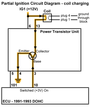
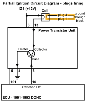
The two diagrams below show a very simple and partial view of the ignition circuit close to the PTU. The NPN transistors in the PTU both amplify and switch the current to the primary windings in the igniton coil. The ECU applies a small current to the transistor base switching the transistor to "on". This allows current to flow from the transistor collector to the transistor emitter and therefore through the coil's primary windings. Using an internal resistor, the ECU controls the current to the transistor base to limit the current in the coil to 6 amps. When it is time to fire the spark plugs, the ECU very quickly withdraws current from the transistor, switching the transistor to "off". As described in the next section, this produces an electric field in the coil's secondary windings.

Ignition system charging    Ignition system firing

Ignition Coils

Automotive ignition coils are step-up transformers that consist of two separate wires wound about a soft-iron core. One wire, called the primary wire, is thicker and has less turns than the other wire, called the secondary wire. A turn is one wrap of the wire around the core. The primary windings surround the secondary windings. Our engines use an inductive discharge ignition system: energy is stored relatively slowly in the primary windings and then released rapidly into the secondary windings.

While the transistors in our ECU and PTU ground the coil's primary wire circuit (also called the Low Tension circuit), current and voltage increase through the primary windings and a magnetic field (flux) is produced around the coil and strengthens until the field maximizes. The current in the primary windings is limited by the ECU to 6 amps. The time (traditionally measured in camshaft degrees) that the ECU holds the coil's circuit grounded is called dwell (analogous to the points being closed in an older distributor system). In our coils, the (dwell) time required to maximize the magnetic field should be around 0.004 seconds (that is, 4 milliseconds or 4 ms). Some modern, high-performance coils need only 2 to 3 ms. Other coils need as much as 8 to 9 ms to maximize the magnetic field. The dwell time is limited by the ECU to no more than 75% of the available time, which is one engine revolution because of our wasted spark ignition system. At 7500 rpm there are 8 ms between coil firings (60,000 divided by 7,500). At this engine speed, dwell time is limited to less than 75% of 8 ms or less than 6 ms. In other words, there is plenty of time even at 7500 rpm, which is above the factory redline, for the coils to completely charge.

When it is time to fire the spark plugs, the ECU releases the Low Tension circuit ground to very quickly stop current in the primary wire. The magnetic field collapses first through the primary windings producing a current in these windings (a process called self induction). This current, typically with a potential in the range of 200 to 400 volts, produces its own magnetic field, which in turn produces an electromagnetic force (emf) in the secondary windings (also called the High Tension circuit) by a process called mutual induction. When there is a complete circuit on the High Tension side, that is when both spark plugs fire, then there is also an induced current generated in the secondary windings. The High Tension voltage is directly proportional to the self-induced voltage in the primary windings times the ratio of the number of turns in the secondary windings to the number of turns in the primary windings, and directly proportional to the resistance in the circuit. A small bit of power is lost to inefficiency in the coil. Typically there are 65 to 135 secondary turns for every primary turn. The final result of the initial magnetic field collapse is a very-high voltage current (with proportionally lower amperage) through the secondary windings and the spark plug wires. The voltage produced in the secondary ignition system is the minimum amount required to produce sparks across the two spark plug gaps. The wasted spark should require from 3,000 to 6,000 volts. The combustion spark may require from 12,000 to over 40,000 volts. Once a spark is produced, resistance in the circuit drops drastically (because the plasma filling the spark gap is conductive) and the energy is quickly dissipated.

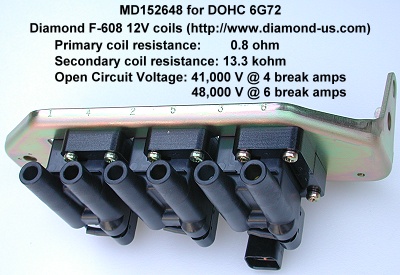
DOHC 6G72 Ignition Coils

Ignition Wires

Ignition wires have four tasks to accomplish: (1) conduct as much of the high-voltage, low-current ignition energy as possible, (2) insulate this energy from metallic and electronic components of the engine, (3) protect the conductor from heat, abrasion, and chemicals, and (4) suppress ignition-generated electromagnetic interference (EMI). Maximum ignition energy is transferred from the coil to the spark plug with the least amount of electrical resistance and the greatest insulating ability (highest dielectric strength). Insulation against voltage arcing or leakage, heat, abrasion, and chemicals is accomplished using an 8-mm or larger diameter sleeve made of special blends of silicone and synthetic material. EMI suppression is accomplished using either higher resistance wires and/or a fine copper-alloy wire spirally wound around a ferro-magnetic impregnated center core. Spiral-wound wires, along with a 0.5" to 1.0" separation between wires, help to minimize induction crossfire between ignition wires.

In a series circuit, such as in the High Tension side of our coils when spark is occuring, voltage drop across each resistor in the circuit is directly related to resistance. Higher resistance means a greater voltage drop across the resistor. Outside of the coil, the resistors are both ignition wires, both spark plugs when they are resistor plugs, both spark plug gaps, and the engine heads and block. The sum of all the voltage drops must equal the voltage available in the electric field produced in the High Tension circuit.

Bosch's book Gasoline-engine management, 1st edition states on page 59 "It is important to remember that higher levels of resistance in the secondary circuit are synonymous with corresponding energy loss in the ignition circuit, and result in a reduction in the energy available for firing the spark plug." The greatest amount of voltage is available at the spark plug gaps by minimizing the resistance in the secondary circuit. This can be accomplished by using wires with the lowest DC resistance and using non-resistor spark plugs. Usually, the problem with low resistance wires (and non-resistor plugs) is that they can do a poor job of suppressing EMI generated by the ignition system. MSD Ignition, Accel, and other manufacturers, have minimized this problem with careful design. For more discussion concerning our ignition wires please see my web page 2-msd-ignwires.htm

Spark Plugs

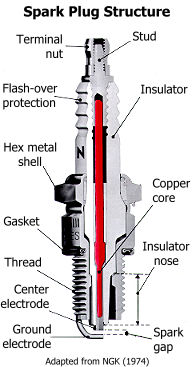
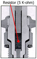
The main parts of a spark plug are the insulator, the metal shell, and the two electrodes. The insulator is made of sintered aluminum oxide (Al2O3) and filler material in order to provide good heat conduction, mechanical strength, resistance to thermal shock, and anti-corrosion. In addition, the insulator must provide a high electrical resistance, about 1 Megohm at 400ºC (750ºF), between the center electrode and the shell. The metal shell has six sides (hexagonal), for use with a socket wrench during installation and removal, and plating for anti-corrosion. The lower section of the shell is threaded for attaching the spark plug to the cylinder head. The length of the threaded section (called the reach, which is 19mm in the 6G72 engine) must closely match the thickness of the cylinder head. The electrodes are a nickel-steel alloy containing chrome, manganese, and silicon, which provide very good anti-corrosion and anti-erosion properties. The ground electrode is welded to the threaded section of the shell. The center electrode is welded to a copper core that runs the length of the electrode and connects to the spark plug wire terminal at the top. The stock spark plugs have a small piece of platinum welded to the tips of both electrodes. The stock spark plug is a resistor-type spark plug, which is indicated by the letter "R" under the NGK letters stamped on the insulator. A 5,000-ohm ceramic resistor is built into the spark plug core to suppress spark-generated electromagnetic noise that can interfere with the car's on-board electronics.

Spark plug structure Spark plug resistor type

The spark plug's primary function is to generate a spark across the gap between electrodes in order to start the combustion process. Combustion is initiated by the flame kernel created from the heat and gas ionization caused by the electrical energy of the spark. The voltage necessary to produce a spark is called the required voltage. It is the job of the ignition system to provide sufficient voltage to the spark plugs, called the available voltage, at the correct time during the compression stroke (typically 5º to 50º BTDC). If the required voltage exceeds the available voltage then a misspark or misfire occurs, that is, there is no spark or a very weak spark. If the available voltage exceeds the required voltage then there is a voltage reserve, and the spark occurs when the required voltage level is met.

The voltage required to produce a spark increases as the spark gap increases and as the compression pressure (intake charge density) increases. The required voltage decreases as the electrode temperature increases and as the electrode diameter decreases. Platinum or iridium discs welded to the steel alloy electrodes effectively decrease electrode diameter and so reduce voltage requirements to produce a spark. This can lead to reduced misfires. See my web pages 2-sparkplugtech.htm for more information about spark plugs. I have a spark plug cross-reference guide for our DOHC engine on this web page 2-sparkplugxref.htm.

Summary

The Mitsubishi-built DOHC 6G72 V6 engine uses an electronically-controlled, distributorless, inductive-discharge ignition system. The engine control unit monitors engine operating conditions to control spark distribution, coil energization time, and ignition timing advance in order to deliver sufficient energy to the spark plugs at the optimal time during the compression stroke. Mitsubishi designed a high-performance ignition system that works well even at high engine speeds. However, the owner can improve the ignition system to deliver more energy to the spark plug gap by using low-resistance wires, such as those made by MSD Ignition with only 40-50 ohm/ft resistance, and by using non-resistor plugs.

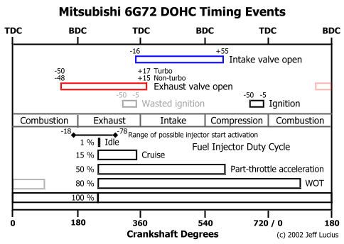
The figure below shows the ignition events for one cylinder in relation to the other engine timing events, piston position, and the four strokes of the Otto cycle.

Mitsubishi 6G72 ignition events

References

Chrysler Corporation, 1988, 1990 Laser Technical Information Manual: Part number 81-699-9002, various pagination.
Chrysler Corporation, 1990, 1991 Stealth Technical Information Manual: Part number 81-699-0114, various pagination. Available on-line at 2-stim.htm.
Kyle Tarryhttp://users.wpi.edu/~ktarry/dsmtech/
Mitsubishi Motors Corporation, 1992, 1993 3000GT Technical Information Manual: Pub No. PYUE9201, various pagination.
Mitsubishi Motors Corporation, 1999, 1992 - 1996 3000GT Service Manual, Vol. 1, Body and Chassis: Pub No. MSSP-001B-96 (1/2), various pagination.
Mitsubishi Motors Corporation, 1998, 1999 3000GT Service Manual, Vol. 1 & 2: Pub No. MSSP-001B-99 (1/2), various pagination.

Back Home Forward

Except for the small gif and jpg images, the content, images, photographs, text, and multimedia displayed are Copyright ©2000-2006 by Jeff Lucius and K2 Software. All rights reserved. No part, section, image, photo, article, or whole of this site may be reposted or redisplayed without permission of the authors.
Page last updated October 31, 2006.