Power Transistor Unit
Removal, Inspection, and Installation
on the DOHC 6G72 engine
in the Mitsubishi 3000GT and Dodge Stealth
by Jeff Lucius
Introduction
The ignition system's purpose is to deliver sufficient energy to the spark plug at the correct time during the compression stroke. For our DOHC 6G72-engined Mitsubishi 3000GT and Dodge Stealth cars the engine control unit (ECU) provides both dwell control (to generate sufficient energy) and timing control (crankshaft and camshaft position information goes directly to the ECU), relieving the power transistor unit (PTU) of this task. The PTU, which can also be called an ignition module or igniter, in our electronic, inductive-discharge ignition system has ony two basic functions to perform: (1) to provide switches, controlled by the ECU, to supply then remove current to each of the three ignition coil primary circuits, and (2) to provide a tachometer signal every time a spark plug fires, which is every 120 crankshaft degrees. In contrast, for example, Toyota often incorporates dwell, timing control, and spark distribution in their igniter units.
The two diagrams below show a very simple and partial view of the DOHC 6G72 engine's ignition circuit close to the PTU. The NPN transistors in the PTU both amplify and switch the current to the primary windings in the igniton coil. The ECU applies a small current to the transistor base switching the transistor to "on". This allows current to flow from the transistor collector to the transistor emitter and therefore through the coil's primary windings. Using an internal resistor, the ECU controls the current to the transistor base to limit the current in the coil to 6 amps. When it is time to fire the spark plugs, the ECU very quickly withdraws current from the transistor, switching the transistor to "off". As described on my web pages 2-ignitionsystem.htm and 2-ignitioncoils.htm, this produces an electric field in the coil's secondary windings.
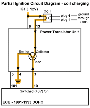
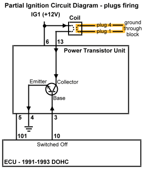
Three ignition coils are used in the distributorless ignition system on our cars. Each ignition coil fires a pair of spark plugs simultaneously: one with the piston before TDC on the compression stroke and the other one with the piston before TDC on the exhaust stroke. The spark during the exhaust stroke is wasted and the basically inert exhaust gas does not combust. This is called a wasted spark ignition system. Inside the PTU there is a power transistor and circuit for each of these coils. The engine speed check connector (2-checkconns.htm) taps into the circuit for transistor and ignition coil "C". While there actually is one pulse per engine revolution through this circuit (the coil fires every revolution), the signal from this check connector must be multiplied by three when monitored by a handheld tachometer (set to 6-cylinder) to determine engine speed.
The same ignition power transistor unit is used on all years and models of the DOHC 6G72 V6 (turbo and non-turbo). It is part number MD152999. I paid $125.31 plus shipping for MD152999 at Tallahassee Mitsubishi (1-888-825-5648 or 850-575-1238).
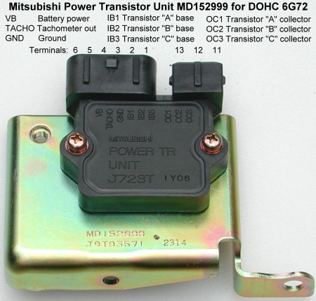
These instructions supplement the service manual's instructions for removing, inspecting, and installing the power transistor unit. Please read all of these instructions before beginning this operation. The suggested tools include: Phillips and slotted screwdrivers, a 10-mm and 12-mm sockets with 6" extension and wrench, 12-mm open/box end wrench, visegrip-type pliers, regular pliers, a small pocket knife or similar tool, and masking tape. If you want to inspect the PTU you will also need an analog or digital volt-ohmm meter, 14" of 18-ga insulated multi-standed wire, a 1.5V C or D cell battery, two jumper wires with 1" aligator clips on the ends, and electrical tape.
Removal
I replaced the PTU at the same time I replaced the ignition coils and these instructions reflect that. You should be able to remove the PTU while leaving the coils in place. However, it may be easier if the coils are removed first.
1. Battery ground cable. With the ignition off, remove the negative battery cable from the battery. Be sure you have security codes for any devices that might need them before you do this.
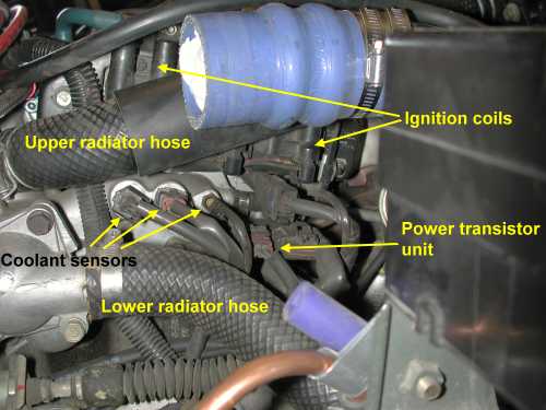
3. Intake hoses/pipes. I removed my ARC2 MAS and air filter, my aftermarket Y-pipe, the "T" hose that the MAS connects to, and my aftermarket metal intake pipe that goes to the front turbo. I place clean rags into all openings (IC pipe, intake hose, turbo, throttle body). This gives pretty good access to the coils and power transitor unit, which is right below the coils. Better access can be had if the upper coolant hose is removed. If you want to remove this hose you can do it the easy, messy way (disconnect the hose at the radiator and catch maybe a quart or two of sticky fluid in rags and containers) or the harder, correct way (remove undercovers and maybe some active aero stuff and loosen the petcock at the lower driver's side corner of the radiator to drain fluid out of the drain hose into a container).
4. Capacitor (if removing coils). Remove the screw that attaches the capacitor to the lower front corner of the bracket. I used visegrip pliers to loosen the screw. The capacitor is attached to the wiring harness. Mitsubishi calls this component the Noise Condenser (illustration 54-550 in CAPS). The part number, MB543146, is the same for all years. The picture below shows the screw that attaches the capacitor (yellow arrow near capacitor) and the two mounting screws (yellow arrows at either end of the bracket).
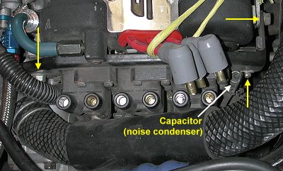
5. Coils harness and ignition wires (if removing coils). Disconnect the wiring harness connector from the bracket by pressing in the lever (underneath) and pulling on the connector. Remove the ignition wires from the coil terminals. Note that the cylinder numbers for each terminal are stamped into the top of the bracket. Toward the back of the bracket a piece of the wiring harness is attached to the bracket using a plastic snap-in piece. I simply cut the plastic piece to disconnect it from the bracket. I did not replace it nor do I know the part number for it. I imagine the dealerships have bins of these things laying around.
6. Front turbo coolant pipe bracket (if removing coils). Remove the 10-mm screw on the bottom of the coils bracket. This attaches a bracket that holds the small coolant pipe for the front turbo center housing rotating assembly.
7. Coils with bracket (if removing coils). Remove the two 12-mm mounting screws that attach the coils and their bracket to the front cylinder head. The shorter one goes in front. Extract the coils and bracket together through the top. This would be much easier if the top radiator coolant hose is removed.
8. Wiring harness. There are two harness connectors on the PTU. The big one, toward the front, has a lever on top. Push down on this lever and pull the connector away from the PTU. You may have to wiggle it a little. The small connector is secured to the PTU with a wire clip, similar to that used on the throttle position sensor harness connector. The wire clip is removed, and installed, from below. It is almost like Mitsubishi tried to make it as difficult as possible to disconnect this connector. Use the pocket knife blade or similar tool to barely slide the clip loose from the connector. Grasp the wire clip with a forceps or similar tool or by hand as you remove it completely. There really is no need for this type of connection. A simple lever-type latch would suffice.
9. Mounting screws. The PTU is secured to the engine using two screws. There is a 10-mm screw underneath near the middle of the bracket and a 12-mm screw at the rear of the bracket. You can see the two holes for these near the bottom of the picture above of the new PTU. To avoid dropping sockets, extensions, and screws I tape the socket to the extension using masking tape. I also take a long piece of masking tape and with the sticky side up push it into the socket and then wrap the rest of tape after giving it a twist around the socket. This way the screw head will stick inside the socket when removed from the bracket. Grasp the PTU and remove it from the engine bay.
Inspection
The service manuals, in section 16 for the 3000GT manuals or in section 8 for the Stealth manuals, offer a few troubleshooting hints plus some service and inspection tests. Under troubleshooting the manuals suggest that a malfunctioning PTU can lead to the following symptom: insufficient or no spark. This suggests that either the PTU works and you get pulses to the coils, or it does not work and the coils do not get pulses. With an analog volt-ohm meter (VOM) you can perform the tests shown below directly on the PTU. These are easy to perform with the PTU off the engine. However, you should be able to perform the tests with the PTU in place and harness disconnected.
The measurements below are designed to test the three power transistors inside the PTU.
Looking at the partial circuit diagram above, we will be testing the collector-emitter continuity of each transistor. If the NPN transistor is operating normally, when sufficient voltage is applied to the base (a minimum of 0.7 volts for a silicon transistor) current will flow between base and emitter. At the same time current can also flow from the collector to the emitter.
For the tests, the ground terminal, noted by "GND" on the PTU case and by the number "4", is the emitter side of all the transistors. The base of each transistor is connected to the terminals labelled "IB1", "IB2", and "IB3" on the PTU case or by the numbers "3", "2", and "1", respectively. The collector of each transistor is connected to the terminals labelled "OC1", "OC2", and "OC3" on the PTU case or by the numbers "13", "12", and "11", respectively. We test for continuity between the collector and emitter by applying +1.5 volts (using a D or C cell "flashlight" battery) to the base terminals with the battery's negative side connected to the PTU ground (terminal 4).
Use an analog-type circuit tester for the three tests. Cut a 14" piece of 18-ga insulated multi-strand wire into two unequal length pieces, such as 8" and 6" (this helps to avoid a short circuit). Strip the insulation off the ends about 1/4 to 1/2 inch. Tape an end of one wire to the positive end of the battery and an end of the other wire to the negative end of the battery. Prop or brace the PTU so that you have good access to the terminals. Clip one of the jumper wires to the end of the wire connected to the positive side of the battery. Clip the other jumper wire to the negative wire from the battery and to terminal 4 (GND) on the PTU. When we clip the positive jumper to IB1, IB2, or IB3, this setup will apply 1.5 volts to the base of the transistor with current through the base-emitter junction. If the transistor is functioning currectly there will also be a complete circuit from the collector to the emitter (ground). When we do not apply a current to the base the connection between collector and emitter should be broken.
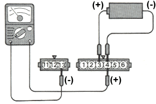 1. Power transistor for no. 1 - no. 4 coil (coil "A"). Set the VOM to measure Ohms and touch the negative lead (black) to terminal 13 (OC1, the collector) and the positive lead (red) to terminal 4 (GND, the emitter). You should see some resistance. Now clip the jumper wire connected to the batttery's positive terminal to terminal 3 (IB1). Measure the resistance between terminals 13 and 4 as before. The resistance should be much less or close to zero. The service manual states there should be continuity with the battery connected to terminal 3 (in fact, the resistance will be very low) and no continuity with the battery not connected (in fact, the resistance will be high). Note on an analog VOM that zero ohms is on the right side of the scale.
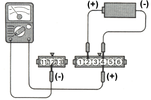 2. Power transistor for no. 2 - no. 5 coil (coil "B"). Repeat the above test except connect the battery positive to terminal 2 and the VOM black lead to terminal 12.
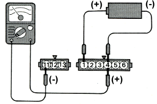 3. Power transistor for no. 3 - no. 6 coil (coil "C"). Repeat the above test except connect the battery positive to terminal 1 and the VOM black lead to terminal 11.
Installation
Installation is basically just the reverse of the removal steps. It may be difficult, especially if you left the upper radiator hose in place, to start some of the screws. To avoid dropping sockets and screws I tape the socket to the extension using masking tape. I also take a piece of masking tape and place the sticky side against the head of the screw. I then insert the screw into the socket, twisting and wrapping the masking tape around the outside of the socket. This way the screw does not fall out of the socket as I start it by hand. Once the screws are started several turns, remove the masking tape and use the socket wrench to finish tightening them. When I reconnected the small PTU harness, I slid the wire clip on from the top instead of from the bottom. I then used some electrical tape to secure the clip. Connect the negative battery cable last. Start the engine and be sure it runs smoothly.
Page last updated April 32, 2004.


 1. Power transistor for no. 1 - no. 4 coil (coil "A"). Set the VOM to measure Ohms and touch the negative lead (black) to terminal 13 (OC1, the collector) and the positive lead (red) to terminal 4 (GND, the emitter). You should see some resistance. Now clip the jumper wire connected to the batttery's positive terminal to terminal 3 (IB1). Measure the resistance between terminals 13 and 4 as before. The resistance should be much less or close to zero. The service manual states there should be continuity with the battery connected to terminal 3 (in fact, the resistance will be very low) and no continuity with the battery not connected (in fact, the resistance will be high). Note on an analog VOM that zero ohms is on the right side of the scale.
 2. Power transistor for no. 2 - no. 5 coil (coil "B"). Repeat the above test except connect the battery positive to terminal 2 and the VOM black lead to terminal 12.
 3. Power transistor for no. 3 - no. 6 coil (coil "C"). Repeat the above test except connect the battery positive to terminal 1 and the VOM black lead to terminal 11.