Turbo Upgrade Guide for the 3000GT/Stealth

by Jeff Lucius

   Topics
         
Introduction
Performance Criteria
MHI Turbo Nomenclature
Ball-Bearing Turbos
Available Turbos
Turbo Wheel-Size Comparison
How to Select
TD05H Kits
Compressor Flow Maps
Where to Buy
Prices and Pictures
1/4-Mile Track Performance
Acknowledgments

Attention manufacturers, modifyers, and owners of turbochargers for the Mitsubishi 3000GT and Dodge Stealth. This web page is the most popular one at my web site. It gets over 100 hits every day. Please contact me regarding any incorrect or incomplete information here for your turbos. Also, have a turbo not listed here? Send an email to website at stealth316 dot com with complete specs and additional information as presented below and I'll consider adding it to this web page.

Introduction

Before spending thousands of dollars on turbo and associated upgrades, I recommend spending $35 on Corky Bell's book Maximum Boost. This is the definitive book on turbocharging. Other books that are very helpful are Turbochargers by Hugh MacInnes ($18) and Motorcycle Turbocharging, Supercharging, and Nitrous Oxide by Joe Haile ($20). The magazine Sport Compact Car ran an excellent series of articles about turbos in the following issues: July 2001, August 2001, September 2001, October 2001, and July 2002. For an excellent explanation of the turbocharger and intercooler setup on the Stealth/3000GT cars, take a look at Roger Gerl's web page http://www.rtec.ch/turbo_basics.html. My Pressurization Primer presents a quick review of the processes and controls involved in pressurizing the intake plenum and manifold. My web page 2-3s-compflowmaps.htm explains how to read and interpret compressor flow maps.

Just as a reminder, when upgrading the turbos on 3S cars and running at higher than stock boost levels, the fuel system must also be upgraded. The minimum upgrade would be 450 cc/min DSM injectors (DSM manual transmission turbo models), an Apex'i AFC (air-fuel ratio controller), and Toyota Supra Fuel Pump (250-260 lph @ 43 psi, 12V). For 15G and larger turbos, 550 cc/min or larger injectors, an ARC2 or VPC, and the Supra (or larger) fuel pump are recommended.

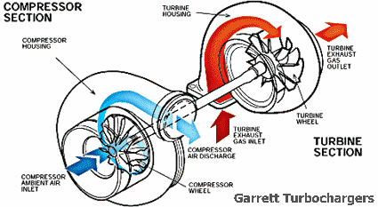
The graphic below by Garrett Turbchargers identifies the operational components of a turbocharger. The CHRA (center housing rotating assembly) that supports the shaft and cools the turbo is not shown. The turbine wheel and shaft are usually a single part. Because the compressor wheel attaches to the shaft, many of the hybrid turbos mentioned later in this guide share the same turbine housing and CHRA but have different compressor wheels and/or different compressor housings.

Garrett: turbocharger operation

Performance Criteria

When selecting a turbocharger for the 3000GT/Stealth, especially if the turbo is a hybrid or not built by the manufacturer of the turbo components, the following items should be considered.
Other than price and quality, the most important considerations for a turbo upgrade are the ease of replacement and the usable airflow range. By easy replacement I mean that the turbo will mount to the stock manifold, thus minimizing upgrade costs. Turbos based on the stock TD04 turbine housing should bolt right to the exhaust manifold. However, other modifications may still be required. I define the usable airflow range as the amount of air available (in cubic feet per minute, CFM) between 10 psi and 25 psi (or pressure ratios of 1.7 to 2.7). This is usually less than the rated airflow at 15 psi.

Additional important factors to consider are efficiency (or how little the compressor heats the air over adiabatic compression alone), surge (when the compressor cannot supply enough air at low engine speeds), and the maximum pressure ratio (PR) the compressor is capable of producing. Compressor flow maps are required to accurately determine efficiency, surge limits, and maximum PR. Most modern turbos operate with maximum efficiencies in the 70% to 80% range. The peak efficiency "island" usually occurs somewhere near the middle of the both the flow range and the pressure ratio range. Surge limits are generally not of much concern for our cars except for the very-largest turbos listed below. Maximum pressure ratio is very important because the relatively small displacement of our 3-L engines requires very-high density ratios (for high effective volume airflow) to achieve performance at the 500 bhp level and beyond.

My use of the term "effective volume airflow" requires some explanation. The volume of the air-fuel mixture that fills the cylinders in our four-stroke, internal-combustion engine is always the same, regardless of engine RPM, throttle position, atmospheric pressure, intake air charge temperature, or boost pressure. That volume is the engine displacement. What changes is the density (and therefore mass) of that air-fuel mixture. At idle that density is very low and under boost that density can be very high. It is difficult to determine the air density inside the cylinders, for the purpose of determining the correct amount of fuel to add, so the air density and volume flow are measured either in the plenum or near the air filter. Typically for the 3000GT/Stealth, volume airflow, air temperature, and air pressure are measured at the Mass Airflow Sensor (MAS) and the engine computer calculates the mass airflow. It is the volume airflow measured at the MAS that I refer to with the term "effective volume airflow". When the air passes through the turbocharger, the volume is decreased and the density is increased; the temperature is also increased. The mass of course remains the same. Volume is further decreased in the intercoolers.

The common way to compare turbochargers is to use the volume airflow rating at 15 psi (or about 2.0 PR). This rating refers to the effective volume airflow I just described. In order to select the correct turbo flow rating for our engines the approximate effective volume airflow must be known for the boost levels we expect to achieve. In the table below, I show the theoretical maximum effective volume airflow for our stock-displacement engine at various pressures. The values in parentheses represent the demand on one turbo for comparison to the flow ratings in the turbo upgrade table presented later. I assume the intake track has an absolute pressure of 14 psi before the turbo (that is, after pressure losses through the air filter and MAS). I also assume that there is (unrealistically) no temperature increase at the plenum associated with the air compression and that there is (again unrealistically) complete filling of the combustion chamber with fresh charge (100% volumetric efficiency, VE, which in this case means "natural capacity"). Since "boosted" air will often be warmer (and so less dense than assumed here) and volumetric efficiency (actually "natural capacity") is almost always less than 100%, these airflow rates below represent the maximum possible without using water or alcohol injection or chilled water-air intercoolers.

Maximum Effective Volume Airflow in CFM - 6 cyl (3 cyl)
2.972 L V6 @ 100% VE, constant temp., 14 psi into turbo
RPM 0 psi boost 10 psi boost 15 psi boost 20 psi boost 25 psi boost 30 psi boost
2000 105 (52) 180 (90) 217 (109) 255 (127) 292 (146) 330 (165)
3000 157 (79) 270 (135) 326 (163) 382 (191) 438 (219) 495 (248)
4000 210 (105) 360 (180) 435 (218) 510 (255) 585 (293) 660 (330)
5000 262 (131) 450 (225) 543 (272) 637 (319) 731 (366) 825 (413)
6000 315 (158) 540 (270) 652 (326) 764 (382) 877 (439) 990 (495)
7000 367 (184) 630 (315) 761 (381) 892 (446) 1023 (512) 1155 (578)
8000 420 (210) 719 (360) 869 (435) 1019 (510) 1169 (585) 1318 (659)

Using reasonable values for natural capacity (VE) for a modified engine, the table below shows the approximate effective volume flow for different combinations of engine speed and boost.

Modified Engine Effective Volume Airflow in CFM - 6 cyl (3 cyl)
2.972 L V6, constant temp., 14 psi into turbo
RPM VE 0 psi boost 10 psi boost 15 psi boost 20 psi boost 25 psi boost 30 psi boost
2000 87% 91 (46) 157 (78) 189 (94) 222 (111) 254 (127) 287 (144)
3000 88% 138 (69) 238 (119) 287 (143) 336 (168) 385 (193) 436 (218)
4000 93% 195 (98) 335 (167) 405 (202) 474 (237) 544 (272) 614 (307)
5000 96% 252 (126) 432 (216) 521 (260) 612 (306) 702 (351) 792 (396)
6000 94% 296 (148) 508 (254) 613 (306) 718 (359) 824 (412) 931 (465)
7000 90% 330 (165) 567 (284) 685 (342) 803 (401) 921 (460) 1040 (520)
8000 85% 357 (179) 611 (306) 739 (370) 866 (433) 994 (497) 1120 (560)

Now we can see why the pressure ratio levels the turbo is able to attain at different flow rates is so important, and why we need compressor flow maps. If the plenum is at 15 psi boost pressure at a certain air temperature, it makes no difference what turbo is used as long as it can meet or exceed the demand listed above at various engine speeds. The mass airflow is the same. The fact that a larger turbo can flow 500 cfm at 15 psi and that a smaller turbo can only flow 400 cfm at 15 psi does not mean the larger turbo can actually flow any more air than the smaller one into the engine at 15 psi plenum pressure. To have higher effective volume airflow, boost pressure must be increased. So what is really important is how much air the turbo will flow at these higher-pressure ratios and this is revealed only in the compressor flow maps and not in the common performance ratings. My web page 2-3s-compflowmaps.htm explains how to read compressor flow maps.

The Unit Converters available from the Tech Page at my web site can be used for conversion to other volume flow and pressure units. If the elevation is much above sea level, then the ambient air pressure will be below the 14 psi I use here, and the same effective volume airflow will be achieved at lower boost pressures. Please see my Pressurization Primer for why. For example, here in Colorado at 5500 feet elevation (12 psi ambient), 17.5 psi boost ([12+17.5]/12) produces the same approximate effective volume airflow (but much less mass airflow) as does 20 psi boost ([14+20]/14) in the table above. My airflow and Fuel Flow Calculators can help in developing other scenarios.

MHI Turbo Nomenclature

Mitsubishi Heavy Industries' (MHI) turbocharger nomenclature, such as TD04-13G-6cm2, requires some explanation. "TD04" and "TD05" refer to the turbocharger housing (either turbine housing or compressor housing or both), including the center housing (or CHRA or cartridge section). There are different styles of the basic housings and these have different suffixes appended to the basic designation, such as TD04L, TD04H, TD04HL, TD05, TD05H, and TD05HR.

TD04 housings have part numbers that start with 49177. TD04L housing part numbers start with 49377. Part numbers for TD04H and TD04HL housings start with 49189. The TD04HL compressor housing is easily distinguished from the others because of the integrated by-pass valve (see the pictures of the SL/MK TD04-18T hybrid below). The TD04LR-16Gk-6cm2 turbo (used on the turbocharged 2.4-L I-4 engine in the new PT Cruiser GT and SRT-4 Neon) is unique and not usable on our cars: the turbine housing is cast into the exhaust manifold, the impeller spins counter-clockwise, and the bypass valve is cast into the compressor housing.

All TD05, TD05H, and TD05HR housings start with 49178. The TD05HR turbine housing (found on the Mitsubishi Lancer Evolution IV through VIII) is a twin scroll design. All the other TD04 and TD05 turbine housings have a single volute in the turbine housing. Like the TD04LR, the "R" in the designation refers to the fact that the turbine wheel spins in the reverse direction (counter-clockwise) compared to the standard TD05H turbine.

The MHI part numbering system, and the possible combinations, can be somewhat overwhelming and confusing. For example, the MHI Sport Turbo Upgrade for our cars is usually referred to as the TD04L-13G-6cm2. This turbo clearly has the standard TD04 (49177) housings (at least by external appearances). However, both the stock TD04-09B-6 and the upgrade TD04L-13G-6 use the 49377 cartridge (but note the different complete part numbers) from the TD04L turbos. TD04 turbos used in other cars (even some other TD04-09B turbos) use the 49177 cartridge.

The "13G" in the model name refers to the compressor wheel. The "13" is the size and the "G" is the style. The 13G wheel has an exducer (or base) diameter or 2.000" and an inducer diameter (air intake opening) of 1.580". All MHI wheels I have seen have 12 blades. Blades are always evenly spaced, but the pitch and height of the blades can change between models. "B"- and "C"-style compressor wheels have all blade tips at the same height. "G"-, "Gk"-, and "T"-style wheels have blade tips at two heights, alternating high and low.

Mitsubishi does not seem to use seperate designations for different size turbine wheels, other than the TD04, TD04H, TE04, TD05H, etc., designation. The "6cm2" in the model name is similar to the A/R ratio used by other manufacturers. The "A" in an A/R ratio is the cross-sectional area of the smallest intake passage in the turbine housing before the passage spreads around the circumferential volute that leads to the turbine wheel. The "R" in the ratio is the distance from the center of the "A" to the center of the turbine wheel. The MHI "6cm2" designation is just the "A" in the A/R ratio, that is, it is just the cross-sectional area. Like A/R, the smaller the size of the "cm2" number, the faster the exhaust gases will discharge onto the turbine wheel, and so the faster the spool up will be (less "lag"). The size of the "cm2" number or the A/R ratio also determines the amount of exhaust gas backpressure and, thus, reversion into the combustion chamber. A larger "cm2" number (or larger A/R) means less backpressure at high exhaust flow. Extreme Turbo says that the TD05H-7cm2 housing is equivalent to a 0.50 A/R. The Rocky Mountain DSM turbo guide presents the following conversion between Mitsubishi's "cm2" number and the standard A/R.

Ball-Bearing Turbos

Conventional turbos, including all MHI TD04 and TD05 turbos, use sleeved journal bearings in the CHRA to support and protect the rotating shaft and to provide resistance to thrust loading. The bearings must carefully position the turbine and compressor wheels very close to the contours in their respective housings at speeds over 100,000 RPM. Oil from the engine is used as a lubricant to reduce friction on the bearing surfaces and to cool the CHRA. Various seal systems are used to prevent the oil from entering the turbine and compressor housings and to reduce the flow of exhaust gas and compressed air into the CHRA. Very often (and in all MHI TD04 and TD05 turbos), engine coolant circulates in a jacket through the CHRA to provide additional cooling. The maximum recommended operating temperature (maximum exhaust gas temperature) of nearly all turbos is 950ºC (1742ºF).

Ball-bearing rotating assemblies offer an alternative to conventional rotating assemblies. Garrett, Turbonetics and IHI manufacture ball-bearing CHRAs. The Garrett and IHI ball-bearing CHRA replaces the sleeved journal bearings with two ball bearings housed in a fully-floating bearing cartridge assembly. The Turbonetics ceramic ball-bearing CHRA utilizes a single, ceramic, angular-contact ball bearing on the compressor side and a floating bearing on the turbine side. Both ball-bearing designs allow greater mechanical efficiency of the rotating assembly, due to reduced friction, and therefore better transient response (that is, faster spool up and much less "lag"). Because ball-bearing turbos eliminate the thrust bearing with ball bearings that have a very-tight clearance between the bearing and shaft, thrust load capacities are improved as much as three-fold in the dual-bearing design and up to 50-fold in the ceramic bearing design. This increases the ball-bearing turbo's resistance to shock loading, allowing it to operate over a wider range of conditions, including higher pressure ratios. In short, ball-bearing turbos spool much faster, operate over a wider range of pressure and flow conditions, and last longer than conventional-bearing turbos. The downside of ball-bearing turbos is that the CHRA is not serviceable in the United States at this time. Ball-bearing turbos also cost more than similarly-sized conventional-bearing turbos.

The HKS GT2835 hybrid is used on the Toyota Supra Turbo and rarely on the 3000GT/Stealth. The price of the GT2835 kit (from SupraStore.com) is somewhat prohibitive at over $9000 list price or about $7900 when "on sale" (this kit includes 2 turbos, external wastegates, a Supra downpipe, and other Supra-related parts). DN Performance markets the IHI RHF5 and RHF55 ball-bearing turbos as part of a kit for our cars, which includes two turbos plus new manifolds and exhaust fittings, for about $4000-4500. The RHF55 turbos are used on Subaru rally cars.

Available Turbos

Other than the model name, there is often little other information available except for the rated CFM flow at 15 psi or 2.0 pressure ratio. Very often the manufacturer of a custom turbo is protective of its design. Fortunately, other information can be estimated solely from the rated flow number. The surge point at 15 psi is often about 1/4 the value of the rated flow. For some designs, such as the T04E "60", the surge point is closer to 1/3 the rated flow. For the IHI ball-bearing turbos, the surge limit is about 13 to 18 percent of the rated flow. Turbos that are a size appropriate for our engines usually have a maximum pressure ratio of 2.8 to 3.1 (or 26.5 to 31 psi boost at sea level before pressure losses in the intercooler system). Also, the CFM flow where a wide range of pressure ratios, from 1.7 to 2.7 (10 to 25 psi boost before IC pressure losses), is available is somewhat less than the rated flow at 15 psi. This practical "maximum" CFM flow is usually about 90 to 95 percent of the rated flow. The choke flow is the maximum amount of volume flow the turbo can produce at any pressure ratio.

The rated flow values below are ones that I have measured on compressor flow maps or have found in the literature (publications, web sites, message boards, email lists, personal correspondence). If any reader has evidence of other values then please send an email to website at stealth316 dot com so that I can update this table. I calculated the estimated minimum and the practical maximum from the rated flow or picked it off the compressor flow map when available. A word of caution should be mentioned concerning flow values for hybrid or custom turbos (that is, those turbos that are not standard production by manufacturers). Flow values can be quite different for a particular compressor wheel when it is installed in a housing other than the one the manufacturer designed it for or if the housing has been modified somehow.

I have divided the turbocharger list below onto two parts; those turbos that are based on the TD04 turbine housing, and so will bolt right to the exhaust manifold, and those that use another turbine housing and require other-than-stock manifolds. If an exhaust manifold is made that accepts the Mitsubishi TD05H flange, then there are other turbine/compressor combinations available than the ones listed below; check out DSM suppliers for these. Note that there are two styles of TD05H turbine housing flanges, one with three mounting bolts ("Subaru-spec" I call them) and one that uses four bolts (stock on DSM cars).

There may be options available that affect the performance of the turbo. These include porting the turbo housings, manifolds, or exhaust housings/pipes (can increase overall flow), clipping the turbine blades (can reduce turbine-induced backpressure for better flow at high engine output, but usually increases lag, and always decreases turbine efficiency), and larger flapper valves (can reduce boost creep). There are other characteristics that I either do not discuss below or do not go into detail. These include wheel characteristics such as compressor wheel tip height (which can effect efficiency and spool up) and number of turbine wheel blades (which can affect turbine airflow restriction), the exhaust housing discharge opening size and A/R (which affects spool up and airflow restriction), and the compressor diffuser characteristics. It is best to discuss these options and design features with the turbo supplier to see if they are appropriate for your engine and its intended use.

Click on the check mark to see the "raw" compressor flow map for that turbocharger. The flow maps for the TD04-09B, TD04-13G, TD05H-14B, and TD05H-16G (small wheel) were supplied by Joe Gonsowski and Garry McKissick with Mitsubishi Motor's permission. Mikael Kenson supplied the TD04H-18T flow map. The other flow maps were found on the internet without credits. My web page 2-3s-compflowmaps.htm presents these same flow maps rescaled for cfm flow and with engine demand lines superimposed.

Turbochargers Available for the Mitsubishi 3000GT/Dodge Stealth
Name Min CFM
@2.0 PR
Rated CFM
@2.0 PR
Practical
Max CFM
Choke
Flow
CFM
Compr.
Flow
Map
Source Comments
Stock manifolds retained
TD04-09B-6cm2 80 275 250 280 raw TD04-09B MHI - stock on USA VR-4 and TT
- right-side number: 49177-02310 or 49177-02300
- left-side number: 49177-02410 or 49177-02400
- cartridge number: 49377-08020
- turbine and shaft: 49177-30130
- repair kit number: 49177-80400
- rotor is 1.57"/1.86" (TD04)
TD04-13G-6cm2 90 360 324 375 raw TD04-13G MHI - stock on European and maybe Japanese VR-4
- aka: Mitsubishi Sport Turbo
- right-side number: 49177-00320
- left-side number: 49177-00420
- cartridge number: 49377-08040
- repair kit number: 49177-80400
- 1989-1994 Eclipse 4G63 2.0L Automatics had TD04-13G-5cm2 (turbo 49177-01901 with cartidge 49177-09010)
- rotor blade length is 5 mm
- rotor is 1.62"/1.86" (TD04L)
GT347 93 370 330   raw TE04H-13C GTP - GTP does not release compressor information
- Basically a "13G-class" turbo
- Mitsu TE04H 13C compressor wheel
- TD04 turbine housing and center section
- Just a guess at CFM
GT357 Magnum 120 400 350 405 raw T3 50 Trim GTP - GTP does not release compressor information
- Basically a "15G-class" turbo
- Garrett T3 "50" Trim compressor wheel
- TD04 housings and center section
- GTP claims 480 CFM rated flow, but the compressor wheel
size suggests a flow rating of about 400 CFM
- Garrett flow map numbers shown for T3 "50" Trim
- TE04 turbine wheel
TD04-13T-6cm2 ~106 ~428 ~405 ~445 raw TD04H-13T VAR - Flow is similar to the 15G and 15C
- This is a hybrid turbo with flow characteristics varying depending on the manufacturer
- Subaru WRX 13T compressor housing
- Bored TD04-9B turbine housing with 13T TD04L wheel
- Turbine inducer blade length is 6 mm
- Requires modifications:
   - to turbocharge housings
   - wastegate relocation brackets with extension bosses
   - adapt IC pipe to rear turbo
   - notch out of upper intake support bracket near rear turbo
- Rob Beck manufactures these hybrids; for more info see
   http://www.3si.org/forum/showthread.php?t=228909
TD04-15G-6cm2 106 428 405 445 raw TD04H-15G TEC
VAR
- This is a hybrid turbo with flow characteristics varying depending on the manufacturer
- TD04H flow map numbers shown
- Actual flow rating may be closer to 400 cfm for some examples
- on-car performance depends on rotor used
TD04HL-16T-6cm2 120 435 400 450 raw TD04H-16T   - TD04HL compressor housing with integrated by-pass valve
- TD04 turbine housing and center section
- Requires modifications to :
   - front engine mount (must be ground a few mm)
   - oil supply lines to both turbos
   - coolant supply and return lines to both turbos
   - right plenum stay must be trimmed
   - rear IC pipe (cut then mount with clamps & 2" ID hose)
   - intake hoses (remove coupler, stretch to fit over compressor inlets)
TD04-17G-6cm2 118 450 425 ?480?   TEC
VAR
- Just a guess at CFM; actual flow may be less
- This is a hybrid turbo
- Flow characteristics vary depending on the manufacturer
TD04HL-18T-6cm2 130 488 450 500 raw TD04H-18T SLT - TD04HL compressor housing with integrated by-pass valve
- TD04 turbine housing and center section
- Requires modifications to :
   - front engine mount (must be ground a few mm)
   - water and oil lines to rear turbo
   - rear IC pipe (cut then mount with clamps)
   - intake hoses (stretch to fit over compressor inlets)
   - AC line on the firewall (re-routed)
   - the passenger's-side radiator fan (replace with a thinner one)
GT368SX 150 490 460 500 raw T3 60 Trim GTP - GTP claims over 600 CFM rated flow
- The 16G-size comp. wheel size suggests a flow rating of about 500 CFM
- Garrett flow map numbers shown for T3 "60" Trim
- Construction information provided by Todd Shelton from
results of disassembly by two different turbo shops
   - Garrett T3 "60" Trim compressor wheel
   - TE04H turbine wheel in bored TD04 housing
   - MHI center section
- Requires an install kit
- Requires modifications to :
   - right plenum stay must be trimmed
   - both water feed lines need to be relocated and re-shaped or replaced pipes with hoses
   - front motor mount must be trimmed or use GT PRO replacement
   - a radiator fan support may need to be trimmed
   - intercooler pipes at the turbo must be larger
   - compressor housings may have to be clocked (rotated with respect to exhaust housing)
TD04HL-19T-6cm2 105 500 430 550 raw TD04H-19T   - TD04HL compressor housing with integrated by-pass valve
- TD04 turbine housing and center section
- Requires modifications to :
   - front engine mount (must be ground a few mm)
   - oil supply lines to both turbos
   - coolant supply and return lines to both turbos
   - right plenum stay must be trimmed
   - rear IC pipe (cut then mount with clamps & 2" ID hose)
   - intake hoses (remove coupler, stretch to fit over compressor inlets)
Requires new manifolds
IHI RHF5 50 382 363 ?415? RHF5 DNP - ball bearing center section
- kit has new manifolds and exhaust housings
- exhaust housings eliminate pre-cats, keep O2 mounts
- manifolds fit TD04L (3-bolt), TD05H (3-bolt), and RHF turbos (not stock 9B housings though)
- IC pipes need to be modified
TD05H-14B-6cm2 125 430 385 500 raw TD05H-14B MHI - stock on 1st gen DSM cars
- number: 49178-01030
- cartridge number: 49178-09010
- repair kit number: 49178-81100
TD05H-14G-6cm2 150 470 420 480 raw TD05H-14G MHI - number: 49178-01750
- cartridge number: 49178-08620
- repair kit number: 49178-81200
IHI RHF55 85 477 410 ?500? RHF55 DNP - Flow is from IHI rating at 2.0 PR and 65% eff.
- ball bearing center section
- kit has new manifolds and exhaust housings
- exhaust housings eliminate pre-cats, keep O2 mounts
- manifolds fit TD04L (3-bolt), TD05H (3-bolt), and RHF turbos (not stock 9B housings though)
- IC pipes need to be modified
GT28RS 62-Trim 150 495 450 550 GT28RS 62-Trim GT - the Garrett "Disco Potato"
TD05H-16G-7cm2 145 520 470 520 raw TD05H-16G small wheel MHI - small 1.830"/2.365" compressor wheel
- number: 49178-05200
- cartridge number: 49178-09090
- repair kit number: 49178-81200
TD05H-16G-7cm2 150 520 445 560 raw TD05H-16G VAR - large 1.892"/2.680" compressor wheel
ETA12 220 525 475 525 t04B S-trim DSM - Garrett/ETA compressor housing
- Garrett TO4B S-Trim compressor wheel
- TD05H-7cm2 turbine housing
- Garrett center cartidge
TD06H-16G-7cm2 138 550 495 560 raw TD06-16G VAR - large 1.892"/2.680" compressor wheel
AAM GT30R 200 570 525 600 GT35 48-trim   - custom Garrett GT35 48-trim compressor wheel
- Garrett T04B compressor housing
- TD05H-7cm2 turbine housing
- Garrett ball-bearing center cartidge
TD05H-16G6-7cm2 150 580 530 625 raw TD05H-18G MHI - With the TD05H-7cm2 exhaust housing it is used on the Lancer Evolution 3. With the TD05HR twin-scroll housing it is available on Evo 4 to 8
- Compressor wheel is aluminum with thinner blades
than standard 16G
- Turbine wheel is Inconel (steel alloy)
TD05H-18G-7cm2 ~150 ~590 ~525 ~640 raw TD05H-18G MHI - flow map is speculation
HKS GT2835 210 600 555 636   GT - custom Garrett GT35 56-trim compressor wheel
- Garrett T04E compressor housing
- custom Garrett GT30R 90-trim turbine wheel
- Garrett turbine housing with T25 flange
- Garrett ball-bearing center cartidge
TD05H-20G-7cm2 163 650 550 680 raw TD06-20G VAR - TD05H 17C compressor housing
DNP - DN Performance
DSM - DSM Performance/Extreme Turbo
GTP - GT-PRO Performance Tuning
IHI - Ishikawajima-Harima Heavy Industries (Warner-Ishi)
MHI - Mitsubishi Heavy Industries
SLT - SL Turbo and Mikael Kenson
TEC - Turbo Engineering Corporation
VAR - various aftermarket sources
GT - Garrett Turbochargers


Turbo Wheel-Size Comparison

I need more measurements to complete this table. Please send an email to website at stealth316 dot com if you have additional information or corrections. The turbos are listed in order of increasing compressor wheel inducer diameter.
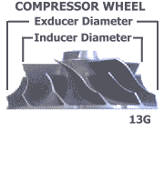
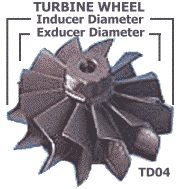
In general, larger wheels tend to take longer to spin up due to their larger inertia. Larger wheels also tend to spin slower to produce the same flow as smaller wheels. Wheel speed is ultimately limited by the speed of sound; the outer tips of the wheel must not exceed mach 1. The design (shape and height) and number of blades also affect wheel performance, but this is beyond scope of this web page and the table below. Wheel "trim" refers to the squared ratio of the smaller diameter divided by the larger diameter times 100. Generally, for a given compressor exducer size, the larger the trim number the more flow the wheel has. For compressor wheels, larger trim also tends to mean slightly lower efficiency. For "families" of turbine wheels (those with the same inducer diameter), larger trim usually means better flow with less backpressure but with less energy recovered from the exhaust flow, and longer spool time.

Compressor wheel dimensions   Turbine wheel dimensions
Turbocharger Wheel-Size Comparison
Turbo Compressor Turbine
Wheel Inducer
Diameter
(in.)
Exducer
Diameter
(in.)
Trim Housing Wheel Exducer
Diameter
(in.)
Inducer
Diameter
(in.)
Housing
TD04-09B 9B 1.365 1.930 50 TD04-09B TD04 1.57 1.86 TD04-6cm2
TD04-13G 13G 1.580 2.000 62 TD04-13G TD04L 1.62 1.86 TD04L-6cm2
GT347 TE04H 13C 1.580 2.087 57 TD04-09B bored TD04 1.57 1.86 TD04-6cm2
TD04-13T 13T 1.597 2.203 53 TD04HL-13T TD04HL 1.80 2.05 TD04-6cm2
TD04-15G 15G 1.625 2.187 55 TD04-13G bored TD04L 1.62 1.86 TD04L-6cm2
TD04H-15G 15G 1.625 2.187 55 TD04H-15G TD04H 1.735 2.042 TD04H-6cm2
NA Hitachi HT12 1.638 2.244 53 TD04-09B bored NA NA NA NA
TD04H-15C 15C 1.654 2.187 57 TD04H-15C TD04H 1.735 2.042 TD04H-6cm2
GT357 Magnum T3 "50" Trim 1.674 2.367 50 TD04-13G bored TE04H 1.88 2.01 TD04-6cm2
TD05H-14B 14B 1.695 2.285 55 TD05H-14B TD05H 1.93 2.20 TD05H-6cm2
TD04-16T 16T 1.713 2.205 60 TD04HL-16T TD04L 1.62 1.86 TD04L-6cm2
TD04-18T 18T ? ? ? TD04HL-18T TD04L 1.62 1.86 TD04L-6cm2
TD04-17G 17G 1.744 2.382 54 TD04-13G bored TD04L 1.62 1.86 TD04L-6cm2
TD04-19T 19T 1.809 2.283 63 TD04HL-19T TD04L 1.62 1.86 TD04L-6cm2
TD05H-14G 14G ~1.80 2.285 ~62 TD05H-14G TD05H 1.93 2.20 TD05H-6cm2
RHF5 F5 1.812 2.375 58 RHF5 F5 1.875 2.065 RHF5-6cm2
RHF55 F55 1.812 2.375 58 RHF55 F55 1.875 2.065 RHF55-6cm2
TD05H-16G "small" 16G small 1.830 2.365 60 TD05H-16G TD05H 1.93 2.20 TD05H-7cm2
GT368SX T3 "60" Trim 1.830 2.367 60 Garrett T3 TE04H 1.88 2.01 TD04-6cm2
Disco Potato GT28RS 1.860 2.362 62 Garrett GT NA NA NA NA
TD05H-16G "large" 16G large 1.892 2.680 50 TD05H-16G TD05H 1.93 2.20 TD05H-7cm2
TD05H-18A 17C 1.900 2.680 50 TD05H-16G bored TD05H 1.93 2.20 TD05H-8cm2
TD05H-16G6 (Evo 3) 16G6 1.902 2.680 50 TD05H TD05H 1.93 2.20 TD05H-7cm2
ETA12 TO4B S-Trim 1.904 2.750 48 Garrett T3 ? ? TD05H-7cm2
GT35 48-trim 71-mm custom GT35 1.936 2.795 48 Garrett T04B TD05H 1.93 2.20 TD05H-7cm2
TD05H-18G 18G 1.992 2.680 55 TD05H-18G TD05H 1.93 2.20 TD05H-7cm2
TD05H-20G 20G 2.070 2.680 60 TD05H-17C TD05H 1.93 2.20 TD05H-7cm2
HKS GT2835 custom GT35 2.092 2.795 56 Garrett T04E GT30R?
trimmed
2.016 2.224 Garrett
GT35 52-trim 76-mm GT35 2.158 2.992 52 Garrett GT NA NA NA NA
GT42 56-Trim GT42 2.769 3.700 56 Garrett GT NA NA NA NA
GT42 53-Trim GT42 2.924 4.016 53 Garrett GT NA NA NA NA

MHI Turbine Wheels
Wheel Exducer (in.) Inducer (in.) Trim Notes
TD04 1.57 1.86 71 wheel height is less than the others
TD04L 1.62 1.86 76  
TD04H 1.74 2.04 73  
TD04HL 1.80 2.05 77  
TE04H 1.88 2.01 87  
TD05H 1.93 2.20 77  

How to Select

So what can be done with all this information? You can determine the turbo that is appropriate for your car's use. First let me say that one group of turbos (say the TD05 for example) is not better than another group of turbos (say the TD04 or GT PRO hybrids). Each group, and each turbo, is optimized for certain applications. If possible, you should work with the manufacturer or vendor to be sure that a turbo's characteristics are optimized for your application.

Generally, the turbos that flow more air have larger compressor wheels and sometimes larger turbine wheels. These larger turbos will produce their best flow at higher engine loads and RPM. This is often perceived as "lag" to the driver. The smaller turbos will spool up quicker (less "lag") but will produce less flow at higher engine loads and speeds. To estimate the amount of power a single turbo can support, multiply the rated flow at 15 psi by 0.6 to 0.65. For example, the IHI RHF55 flows about 477 cfm at 15 psi; this would be good for about 286 to 310 bhp (at higher boost levels of course), or about 572 to 620 bhp in our cars that use two turbos.

Let's compare the stock TD04-09B turbo to the popular TD04-15G at 15 psi boost. The maximum effective volume flow table above indicates that the stock turbo should be running out of air somewhere near 5000 RPM. After this point, boost values will decrease, as the stock turbo cannot supply the required airflow. On the other hand, the 15G should be able to hold 15 psi boost clear to 7000 RPM. If we increase boost to 20 psi (with all the proper precautions such as an increased-capacity fuel system, forged pistons, and gauges) the stock turbo falls short by 4000 RPM but the 15G should be good to about 6000 RPM or so. For higher boost levels, turbos larger than the 15G may be the best choice, such as the GT368SX hybrid, the TD05-16G adaptations, and the IHI RHF55.

This bears repeating one more time. Just because a turbo is rated at 650 CFM @ 15 psi (for example) does not mean that the turbo flows that amount of air in our 3L V6 engine at 15 psi plenum pressure. The engine mass airflow is determined by the displacement, the RPM, the volumetric efficiency, and the air density (or plenum air pressure and temperature). At a given RPM and at the same plenum air pressure and temperature, the same amount of airflows regardless of which turbo is used.

TD05H Kits

TD05 turbos are used on the DSM cars and so are fairly easy to find, modify, and rebuild. If you decide that a TD05-based turbo is the best model for your car, then you will have to either modify the turbo-mounting flange on the stock manifolds or use custom-built manifolds. Altered Atmosphere Motorsports (AAM) offers manifolds that use larger-diameter and equal-length runners to optimize flow for a real improvement over the stock manifolds. The AAM kit uses the "standard" TD05 turbos (like found on DSM cars) and use an integral wastegate, as do the stock TD04 turbos.

GReddy also offers a TD05 kit (for about $2100) but it is substantially different than both the AAM and the DN Performance kits. The GReddy TD05 turbos cost about $1800 (for the pair; 16G), have a 3-bolt manifold flange (rather than the 4-bolt flange found on DSM TD05 turbos), and require an external wastegate (about $1200 for two type-s wastegates) that is incorporated into the exhaust manifold. I do not know if the GReddy 3-bolt pattern is the same as the "Subaru-spec" 3-bolt TD05 pattern.

The manifolds marketed by DN Performance are available for the TD04L and TD05 turbine housings that use the Subaru-spec 3-bolt manifold flange with integral wastegates. As far as I know, the Subaru-spec 3-bolt pattern is not the same as the TD04 3-bolt pattern. DN Performance can have manifolds and exhaust fittings made that can be used with the stock TD04 or DSM TD05H turbos for about $2700.

TD05H Exhaust Kits for the 3000GT/Stealth
Manufacturer Price Coments
GReddy $2100 - 3-bolt TD05H housing
- external wastegate required
DN Performance $2700 - 3-bolt TD05H housing
- internal wastegate
- no pre-cat in rear exhaust fitting
- IHI RH/RHF and TD04L turbos also bolt on
- choice of material and finish
AAM ? - 4-bolt TD05H housing
- internal wastegate
- equal-length runners


Compressor Flow Maps

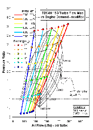
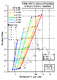
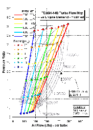
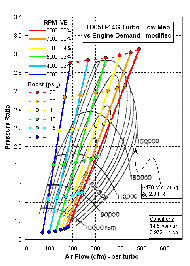
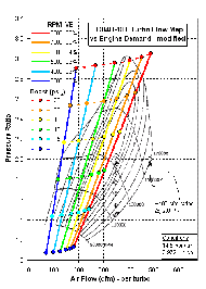
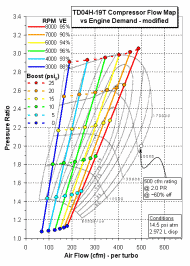
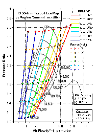
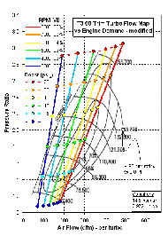
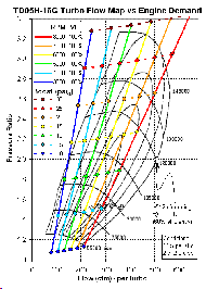
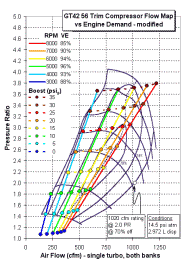
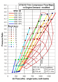
On the compressor flow map, the horizontal axis represents the amount of uncompressed air entering one turbo, usually expressed in either cubic meters per second (0.1 m3/s = 211.888 cfm) or pounds per minute (10 lb/min = 144.718 cfm at 85.31ºF and 13.9487 psi). The vertical axis represents the amount of air compression that occurs inside the turbo; it is the ratio of the air pressure right after the turbo to the air pressure right before the turbo. The curved lines with labels such as 110000 are the rotational speed of the compressor wheel. The elliptical curves with labels such as 60% represent the efficiency of the compressor, or how well the compressor achieves pure adiabatic heating of the air (higher numbers are better and mean less extra heating of the air). The "raw" flow maps that I use here can be seen by clicking on the check marks in the table above. For a more complete explanation of compressor flow maps, please look at my web page 2-3s-compflowmaps.htm.
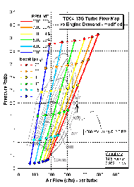
Inside the turbo, air is compressed; volume decreases and temperature increases. The compressed air leaves the turbo and flows into the intercooler system, where air density increases because the temperature is greatly reduced and the pressure only slightly reduced, and eventually flows into the intake manifold. For our engine, each turbo only needs to supply enough airflow for half of the stock 2.972-L displacement. The engine total volume airflow, which is referred to here as the engine demand, is determined by the displacement, the RPM, the volumetric efficiency, and the air pressure in the manifold (total mass flow also would factor in air temperature).

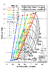
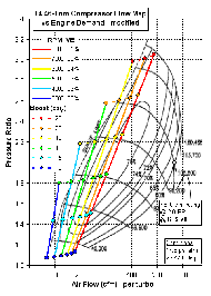
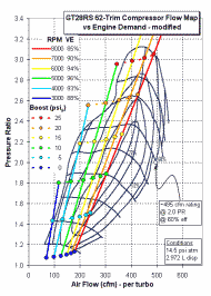
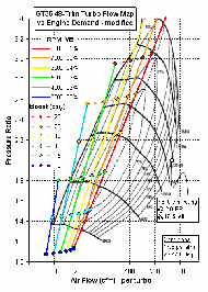
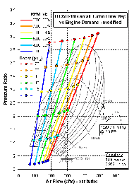
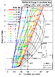
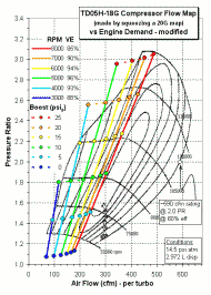
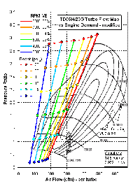
In order to predict engine demand for a modified engine, I estimated the volumetric efficiency (VE) of highly modified 6G72 engines and the pressure losses from the air filter to the turbo and in the intercooler system. The engine demand lines were calculated using half the displacement (so they are are applicable for one turbo) and the following volumetric efficiencies at wide open throttle or full load: 87% at 2000 rpm, 88% at 3000 rpm, 93% at 4000 rpm, 96% at 5000 rpm, 94% at 6000 rpm, 90% at 7000 rpm, 85% at 8000 rpm. The charts below show this predicted engine airflow as a function of compressor pressure ratio (rather than intake boost pressure) at selected engine speeds and assuming 14.5 psi atmospheric pressure. I won't get into the details nor provide the Excel spreadsheets, as the volumetric efficiencies and pressure losses are speculative (though I think reasonable and match reported boost and RPM values by many owners). However, the charts do give you an idea of how these different turbos would perform with the high-performance engine and intercooler setup I have created. Credit for the original presentation format and the spreadsheet design goes entirely to my friend Joe Gonsowski.

The engine boost level (shown as circles on the demand lines) is the gauge air pressure in the intake manifold and is not scaled to the chart's vertical axis. For example, the 15 psi boost levels at the different engine speeds lie above the turbo 2.0 PR line. This is because there are pressure losses both before and after the turbo that vary with engine speed and total airflow and so the turbo must produce more than 15 psi of extra pressure to make 15 psi of boost in the manifold.

In my opinion, a compressor flow map must be available for any turbo that is considered as an upgrade option for our cars. Unfortunately, some manufacturers either do not have or refuse to reveal these maps for their turbos. In addition, many (if not all) turbo shops are forbidden under legal contract to release compressor flow maps by the major manufacturers, such as Garrett and MHI. I have been told the machine used to measure compressor wheel flow costs about one million dollars. Nevertheless, without a map you have only a very poor idea of how suitable the turbo is for your engine and driving style. The compressor flow map does not tell the whole story (for example, turbine performance and lag need to be considered), but it is the basis for making an informed turbo upgrade selection. Ideally, all portions of the engine demand lines in the boost range you plan to use should lie on the flow map. If significant portions of the flow map lie outside of the engine demand lines, the turbo may not be appropriate for our engines.

Click on the image below to view the full-scale image in another window. For easy chart comparison, sequentially click on the thumbnails and then use the "back" and "forward" buttons in your browser.

TD04H-13 compressor flow map
TD04H-13G (26 KB)
TD04H-15G compressor flow map
TD04H-15G (27 KB)
TD04H-16T compressor flow map
TD04H-16T (33 KB)
TD05H-14B compressor flow map
TD05H-14B (27 KB)
TD05H-14G compressor flow map
TD05H-14G (29 KB)
TD04H-18T compressor flow map
TD04H-18T (27 KB)
TD04H-19T compressor flow map
TD04H-19T (40 KB)
T3 50-Trim compressor flow map
T3 50-Trim (28 KB)
T3 60-Trim compressor flow map
T3 60-Trim (27 KB)
T04B S-Trim compressor flow map
T04B S-Trim (32 KB)
TD06H-20G compressor flow map
T4 46-trim (30 KB)
TD05H-16G-large compressor flow map
GT28RS 62-trim (29 KB)
GT35 48-Trim compressor flow map
GT35 48-trim (32 KB)
TD05H-16G-small compressor flow map
TD05H-16G-small (28 KB)
TD05H-16G-large compressor flow map
TD05H-16G-large (29 KB)
TD05H-18G compressor flow map
TD05H-18G (37 KB)
TD06H-20G compressor flow map
TD06H-20G (29 KB)
 

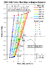
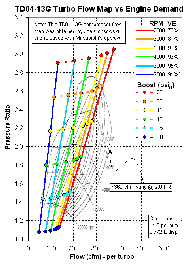
To get an idea of how well the stock engine and TD04-09B and TD04-13G turbos are matched, I created the charts below. I set the volumetric efficiencies to match how I interpret the "dyno" chart supplied by Mitsubishi for 1991 VR4s: 91% at 2000 rpm, 95% at 3000 rpm, 93% at 4000 rpm, 90% at 5000 rpm, 81% at 6000 rpm, 75% at 7000 RPM. Joe Gonsowski obtained the TD04-09B and TD04-13G compressor maps from Mitsubishi.

Estimate of TD04-09B compressor flow map
TD04-09B (23 KB)
Estimate of TD04-13G compressor flow map
TD04-13G (26 KB)

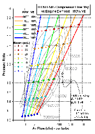
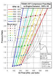
The key to being able to effectively use turbos larger than the TD04-13G is to improve the engine volumetric efficiency at higher engine speeds. This is accomplished by careful upgrading of the exhaust system (port-matched exhaust manifolds, precat removal, better downpipe, free-flowing main cat, better cat-back pipes and mufflers) and the intake system (larger MAS and better filter with an ARC2 or GM MAF Translator, or a VPC setup, better intercoolers and piping, port-matched intake manifold, maybe ExtrudeHoned plenum and intake manifold, maybe head flow work, maybe multi-angle valve seats). Also, some racers have had success with larger valves, adjustable cam gears, and different cams. The best VE that can hoped to be achieved is 100 percent, that is, all of the swept volume is filled with fresh intake air and there is no exhaust gas reversion (admittedly, this ignores combustion chamber volume). The charts below show the maximum possible engine airflow demand with 100% VE at all engine speeds. Our 2.972-L V6 just can't flow more air. If this is not enough air for you, the next step would be a 93-mm bore for a 3.1-L displacement or even a 3.5-L stroker kit. Additional oxygen can also be supplied by N2O (nitrous oxide).

TD05H-14B compressor flow map with 100% VE
TD05H-14B (100% VE) (29 KB)
TD04H-19T compressor flow map with 100% VE
TD04H-19T (100% VE) (40 KB)
TD05H-16G-large compressor flow map with 100% VE
TD05H-16G (100% VE) (30 KB)

OK. One last set of flow maps. The two Garrett GT turbos below, the 94-mm GT42 56-trim and the 102-mm GT42 53 trim, are an example of the flow and boost levels that might be achieved utilizing a single turbo setup for our engines.

GT42 560trim compressor flow map with 100% VE
GT42 56-trim (30 KB)
GT42-53-trim compressor flow map with 100% VE
GT42 53-trim (33 KB)

Where to Buy

Shop around and compare prices and services. For additional vendors, please visit my Links Page for sources of stock, rebuilt, and aftermarket turbos for our cars. Look in the following sections: "Speed Shops and Online Stores that specialize in our cars", "General Performance Products", "Specialty Products", and "Turbo-related".

Retail Vendors and Products
Vendor Products
Alamo Motorsports TD04-13G/15G, TD05H-14G/16G
DN Performance JUN manifolds and exhaust housings for IHI RHF55/RHF5, 3-bolt TD04L, and 3-bolt TD05H
DSM Performance
Mutt, TD05H-16G
Extreme Motorsports TD05H-16G/17C/19C/20G, Frank 1-6
Extreme Turbo & Fabrication remanufacture
Forced Performance TD05H-16G/18G/20G RECOMMENDED FOR REBUILDS
Hahn Racecraft TD04-13G, TD05H-16G
Mach V Motorsports TD04-13G/15G
Majestic TurboChargers remanufacture
MVP Motorsports TD04-13G, GT-357
Performance Techniques remanufacture, repair, service, hybrids RECOMMENDED - REBUILDS, CUSTOM WORK
SL Turbo TD04-18T
Team Rip Engineering TD05H-16G/18G/20G, Frank 1- 6
Texas Rebuild remanufacture, repair kits, TD04-09B/13G/15G, TD05H-16G/17C/20G NOT RECOMMENDED
The Third Coast TD04-13G/15G, GT-347/355/357/368/399
Turbo City remanufacture, repair kits
Turbo Engineering (TEC) TD04-09B/13G/15G/17G RECOMMENDED FOR REBUILDS
Turbo Performance Center HKS and Greddy turbos (TD04-13G)
Turbo Power remanufacture, repair kits
Turbo Specialties remanufacture, "true" TD04-15G (using TD04HL-15G wheels)

Prices and Pictures

The table below shows some approximate prices or price ranges for pairs of various new turbos. Prices for rebuilt turbos may be less. Place your cursor above the camera icon to display a brief description of the picture then click on the icon to display the graphics file in a separate window.

Turbocharger Prices and Pictures
Turbo Approximate Price
for Two ($US)
Pictures
TD04-09B ~$2000 Comparo: 9B vs. 13G, compressor side  Comparo: 9B vs. RHF55, compressor side  Comparo: 9B vs. TD04L, compressor side  TD04C repair kit  TD04 turbine wheel and shaft
TD04-13G $1500-2350 TD04-13G, compressor side, front and rear turbos   another TD04-13G, compressor side, front and rear turbos   Comparo: 9B vs. 13G, compressor side   (Japanese VR4) 13G compressor side   TD04-13G right compressor 1   TD04-13G right compressor 2   TD04-13G turbine wheel   TD04-13G left compressor   TD04C repair kit
TD04-15G $1850-2700 15G, compressor side, front and rear turbos  Another 15G, compressor and exhaust sides  Comparo 1: 15G vs. 368, compressor side  15G turbine wheel clipped  HTML page with five pics of my TD04-15Gs
TD04H-15G $1950-2000 TD04H-15G, compressor side  TD04L compressor housing
TD04-17G $2732  
TD04-18T $2350 (with 9B core) 18T turbo 1  18T turbo 2  18T turbo, compressor and turbine wheels
GT368 $3250 Comparo 1: 15G vs. 368, compressor side
TD05-14B $800+ Comparo: 20G, 16G, 14B compressor housings
TD05-14G $1300 14G turbo
RHF55 $3500 RHF55, compressor and exhaust sides  Comparo: 9B vs. RHF55, compressor side
GReddy TD05 w/ manifolds, wastegates $5100 GReddy turbo kit w/ manifolds
TD05-16G "small" $1200-1650 16G turbo  TD05-16G, compressor side, wheels  TRE 16G turbos  16G compressor wheels  Comparo: 20G, 16G, 14B compressor housings
TD05-16G "large" $1400-2000 TD05-16G, compressor side, wheels  TRE 16G turbos  16G compressor wheels
Level 1 Mutt $2800 Level 1 Mutt  DSM Performance Mutt  DSM Performance Mutt comparison
TD05-20G $1200-2450 TRE TD06H-20G, compressor side  Comparo: 20G, 16G, 14B compressor housings

1/4-Mile Track Performance

Jack "xwing" Tertadian has used 9B, 13G, 15G, and 17G turbos on his cars and reports the following best 1/4-mile times and speeds. With stock TD04-9B turbos Jack ran a best of 12.727 s @ 107.562 mph in his 1993 VR4. Going to TD04-13G turbos, and no other changes, his performance improved to 12.172 s @ 112.890 mph (~16-17 psi boost). When he added the VPC setup and 550 cc/min injectors with the 13Gs, his best speed increased to 12.000 s @ 119.381 mph and his best time dropped to 11.702 s @ 118.061 mph. The TD04-15G turbos (and 20+ psi boost) with 550 cc/min injectors allowed Jack to run a best speed of 11.387 s @ 125.76 mph and best time of 11.303 @ 122.54 mph. Using 720 cc/min injectors with the 15G turbos did not improve Jack's track performance. Jack made these runs in a street car with full interior.

Ray Pampena has run 11.004 @ 121.485 using 15G turbos, a 1991 block bored 0.100" over (3141 cc) with a steel crank and stock rods and pistons, ATR exhaust (no cats), 660 cc/min injectors with an A'PEXi S-AFC, stock ICs and pipes, HKS EVC-IV, modified stock MAS, a custom clutch, and a few more modifications.

With the exception of Matt Monett (DR; using DR650R and GT368SX turbos), Mike Mahaffey (AAM; using TD05H-20G turbos), and Takayoshi Iwasaki (Zesty Racing, using HKS GT2835 turbos), other drivers with cars using the TD04 or TD05H hybrid turbos have not produced substantially better 1/4 mile times or speeds than 15G-equipped cars. For the 1/4-mile records check out Team3S's Fastest 1/4 Mile Times and Import Power Online's Quick List & Highest Dyno Runs web pages. Jack T. did run a 11.219 s @ 124.63 mph with 17G turbos in June 2000. In 1997, Jack ran a 10.81 @ 128.44 mph with 15G turbos and nitrous oxide. Matt Monett, Mike Mahaffey, Jack Tertadian, and Takayoshi Iwasaki have all run the 1/4 mile in less than 11 seconds with top speeds near or over 130 mph.

Below is a Team3S email list post from Jack Tertadian (xwing) that I always found informative and useful. Remember, this post is from 5 years ago and the 1/4 mile runs are from 8 to 10 years ago. Turbo options were more limited for us back then.

The bottom line for me is that MHI TD04-13G-equipped cars (or with turbos in that size and flow class) can produce enough power to get into the high 11's in the 1/4 mile; this meets or exceeds many owner's goals. This size turbo is very responsive on the street and the turbos and required mods are reasonable in price and installation effort. MHI TD04-15G-equipped cars (or with turbos in that size and flow class) can get to near 11-s flat in the 1/4 mile - with the right driver, right drivetrain mods, and right engine mods. The newer turbo options are more exotic and interesting but if affordable do not produce significantly better 1/4 miles times (read that as not significantly more power). Responsiveness on the street and the "fun factor" is another consideration, though. The really big, expensive turbo setups have produced incredibly better 1/4 mile times than 15G setups! But those setups are usually more power and expense and modification hassle than the typical street driver/casual racer is looking for.

----- Original Message -----
From: "xwing"
To: stealth-3000gt@list.sirius.com
Sent: Tuesday, October 26, 1999 12:35 AM
Subject: 9B, 13G, 15G relative performances

The 13G make at least 50+ hp more than the 9B. I did no other changes on my '93 and went from 12.727 @ 107.562 mph to 12.172 @ 112.890 mph quartermile on 8/31/94 going from 9B to 13G. This is somewhat over 50hp, and I did not have the VPC/550 injectors yet, so had to limit boost to ~16-17psi or fuelcut came in. In this configuration, went best of 114.350 mph on 9/27/94, ~65hp more (all stats are NO nitrous in this letter, except as noted).

--I think 9B's can be good for about 410hp at wheels maxxed out with standard stuff.

Once VPC/550 injectors in, 13G's went 12.000 and 119.381 best mph, on 4/8/95; about 500 hp at the wheels; overall, gained about 110 hp with 13G over 9B, but given other changes 13G likely ~100 hp better than 9B. 13G best ET was 11.702 @ 118.061 on 6/6/96; this was through traps in 3rd gear, on the rev limiter. I was the first 3000GT in the 11's 5/17/95 with an 11.937@118.338. --I think 13G can be good for about 510hp at wheels maxxed out with standard stuff.

15G best MPH was 11.387 @ 125.76 11/28/96 at the 1st Annual 3000GT/Stealth vs. Diamond Star Shootout in Temple, TX with the 550 injectors; about 575 hp at the wheels, so 15G make about 75 hp more than 13 G, but note I made some other changes so 15G likely ~40-50hp better than 13G. After that, 720cc injectors did not add any mph to trapspeed, indeed seemed to LOWER speed likely due to over-rich condition-- but lowered EGT a tad (max 1850 F at Temple) which may or may not have been good because knock could at random times mean EGT high due to retard, or due to a true lean mix. Best ET for me with 15G was 11.303 @ 122.54 at DSM Shootout 5/16/97, which I won class in :) full interior, as required by Dave Buschur...Adam Weltz went ~11.25 "no NOS".

--I think 15G can be good for about 580hp at wheels maxxed out with standard stuff.

My car made best 575 or so at wheels no NOS, but that is not "maxxed" because I always had stock intercoolers, no headers, no head/intake/throttlebody porting/ignition/standalone computer--with THOSE parts, my "maxxed out" figures could be somewhat higher...

Best 3000GT/Stealth ET/MPH overall is still my 10.810 @ 128.44 with 15G's, 50hp NOS on 6/3/97; I had the distinct honor of making this pass lined up with the late Jeff Curtis in his Stealth...

I'd not hesitate to get 13G's if desired and price right. The 15G make more topend, and I think they are worth it. 17G and more exotic turbos have yet to put better numbers to the pavement. When they do, we'll see what other mods/weight reductions etc are on the cars doing it. 15G are still unbeaten, both on motor and with NOS; are capable of 125 mph quartermile / 575+ hp AT THE WHEELS no NOS in my car, with only piggyback computer mods/no porting/enginework beyond the boltons. Pretty amazing, really.

Jack Tertadian
Atomic Motorsports :)

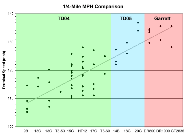
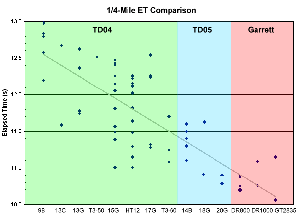
OK, one last comparison of the different turbos. The charts below do not include all the turbos mentioned on this web page, and do include some newer turbos that are not mentioned above. The data were taken from the "quickest" and "fastest" lists noted earlier, and from the 3SI.ORG message board. I made these charts mostly to compare the different exhaust-side housings. I think the comparisons and the trends are useful. It will be interesting to add more data from TD05H-14B, TD05-16G, and TD04-13T turbos. "HT12" represents the DR650 turbo (any version). The "T3-50" is the GT357 Magnum. The "T3-60" is the GT368SX (any version). The "DR1000" is the GT35 52-Trim 76-mm. Turbos are roughly ordered by compressor size.

For determining power, the 1/4-mile terminal speed is a fair judge. There are too many driver and drivetrain factors involved to use elapsed time as a comparision for engine power. The trend as seen in the MPH chart is that turbos with TD05 exhaust housings tend to produce more power than those with TD04 exhaust housings. And the Garrett exhaust housings produce even more power. Note, though, that the highest speed was with the TD06H-20G compressor in a TD05H compressor housing with a TD05H exhaust housing. If a person is staying with the factory TD04 exhaust housing, then the 15G, DR650, 17G, and GT368 would all make good upgrades and similar power, with the 15G probably producing a little less power than the others for the average owner.
Turbos 1/4-mile MPH comparo
Turbos 1/4-mile ET comparo

Acknowledgments

Some of the information presented here was gathered from various email lists, message boards, and vendor web sites. I would like to particularly thank Todd Shelton, Rob Beck, Giuseppe "Joe" Cannella (AAM), Errin Humphrey, Joe Gonsowski, Jack Tertadian, Kyle Edeker, Ray Pampena, Roger Gerl, Tom Stangl (http://www.vfaq.com/mods/Turbo-compare.html), Mikael Kenson, Bob Fontana, DSM Performance, Texas Rebuild, DN Performance, GT PRO Performance Tuning, Team Rip Engineering, Forced Performance, Road///Race Engineering, Garrett Turbochargers, Garrett Performance Products, Ray Hall Turbocharging, IHI Turbo America, Turbonetics, and Saito (MHI part numbers) for their contributions.


Back Home Forward

Except for the small gif and jpg images, the content, images, photographs, text, and multimedia displayed are Copyright ©2000-2005 by Jeff Lucius and K2 Software. All rights reserved. No part, section, image, photo, article, or whole of this site may be reposted or redisplayed without permission of the author.
Page last updated April 23, 2006.