Shock and Strut Removal & Disassembly
on the AWD Mitsubishi 3000GT/Dodge Stealth
by Jeff Lucius
Introduction
These instructions are for removing and disassembling the rear shocks and front struts on the all-wheel drive and all-wheel steering 1992 Dodge Stealth Twin Turbo. For other models, you may have to improvise a little. I have been told that the ECS (Electronic Control Suspension) shocks and struts wear out after about 50,000 to 60,000 miles. Mine had about 58,000 on them when I replaced them. The front struts were leaking oil and had little compression or rebound dampening ability. The rear shocks seemed OK, but it is probably a good idea to replace all at the same time. At a minimum replace both front or both rear at the same time. Each shock and strut cost me about $136 at Tallahassi Mitsubishi (888-825-5648; be sure to ask for the club discount; list price is about $170 each). The new shock or strut does not include all the parts required to mount it to the car. So parts must be transferred from the old shock or strut to the new one.
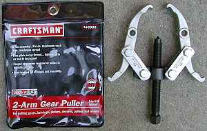
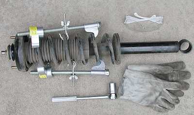
Read all of the instructions and look at the pictures before you begin. The tools required are 1/8" slotted screwdriver, large slip-joint pliers, 12-mm, 14-mm, 17-mm, 17-mm deep, 19-mm, and 19-mm deep sockets, 3-inch and 6-inch socket extensions, a socket wrench, a breaker bar to go over the socket wrench handle, a torque wrench, 17-mm wrench, rubber mallet or hammer, jack stands, jacks, and a little grease. Safety glasses and leather gloves are always a good idea. You may need the following items if you have trouble removing the rear shocks: vicegrip-type pliers, propane torch, gear puller with correct-size washers to protect the threads of the mounting post. A punch or other marking tool may be needed to note the front strut camber settings. If you plan to disassemble the shock or strut yourself, you will also need a spring compressor tool. I either replace screws and bolts in their holes after a part is removed or I use labelled plastic storage containers or bags to keep all the little parts sorted and not lost.
Pre-Removal
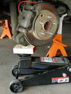
You will need to remove the wheels and support the car. I have instructions for this at this link 2-raisecar.htm. I removed all four wheels and had the car supported by 4 jacks, with four more jacks as secondary support under the side sills. For the rear shocks you will need to remove the access panel on the inside rear compartment side trim panels to gain access to the top of the shock. I already had all my rear trim panels removed (for other reasons) when I replaced the rear shocks the first time. When I had to remove the shocks again after the inside the panels were in place, I did not see a practical way to remove the bolts by just removing the small access panel. I again removed all the inside panels to gain good access to the top mounting bolts.
Rear Shock Removal
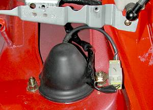
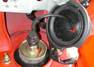
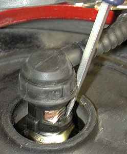
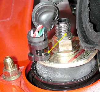
1. Upper mount. At the top of the shock, remove the cap that protects the ECS connection to the piston rod; pry it off by hand. The ECS connector snaps ont the top of the shock. If it does not come loose by squeezing it on its sides then while pulling up a little on the ECS connector with one hand, use a 1/8" slotted screwdriver to gently pry out on the plastic piece that catches in the notch cut into the threads of the piston rod (see pictures below). Remove the 14-mm nut holding the ECS connector harness. Remove the two 14-mm shock absorber upper mounting nuts.
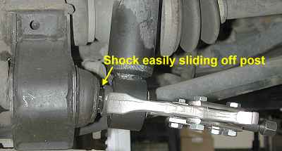
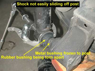
2. Lower mount. Remove the 17-mm shock absorber lower mounting bolt. You may need a breaker bar to do this. Be sure you are trying to rotate the bolt counterclockwise (as you are looking at the head of the bolt). Now if you are lucky, you can apply a little upward pressure on the shock body and push it off the mounting post (or perhaps using a pry bar or mallet). Unfortunately only my new shocks mounted and dismounted this easily. The old left shock came off easily using a gear puller. Use an appropriately sized washer or nut to protect the threads of the mounting post from the gear puller. The old right shock did not come off so easily. The metal bushing was frozen to the mounting post. I used the gear puller to pull the body of the shock off, leaving part of the rubber bushing and the metal bushing behind on the post. I then grasped the metal bushing with a vicegrip-type plier and heated the bushing with a propane torch. Using rotating and pulling force on the bushing, it broke free after about 15 to 20 minutes of heating. I then cleaned up the mounting post with a wire brush.
Rear Shock Disassembly
1. Compress the spring. Use a spring compressor to compress the spring coils to relieve tension on the piston rod tightening nut. Follow the directions on your spring compressor. Be careful to not pinch your fingers. Wear safety glasses. Some auto parts stores and "muffler" shops will also perform this service for you for $10-40 per shock or strut. Plan ahead if you are going to have a shop disassemble your shock or strut.
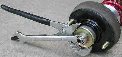
2. Remove the piston rod tightening nut. Use a large slip-joint plier or similar tool to hold the washer still (and the piston rod) while you loosen and remove the retaining nut with a 19-mm socket or wrench. A local shop informed me that there is also a special tool available that inserts into the ECS connector to stop the rod from turning.
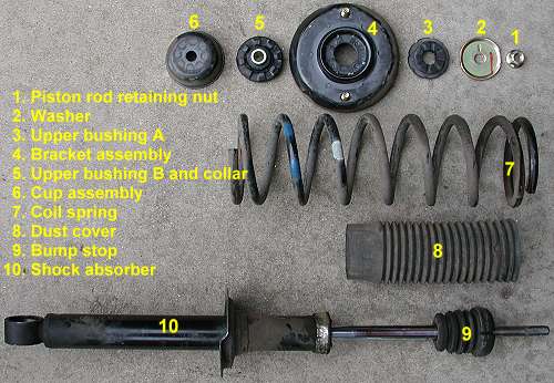
3. Disassemble shock components. The rest of the parts are taken off by hand. In the picture below, the spring pad is not shown; it is still in the underside of the bracket assembly. Transfer the parts you need to your new shock. Use the spring compressor if needed before attaching the retaining nut. Torque the retaining nut to 14-18 ft-lb (20-25 Nm). Be sure the notch on the piston rod is exposed for the ECS connector to lock into it.
Front Strut Removal
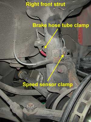
1. Note camber marks. After you have supported the car and removed the wheel, make a note of the camber adjustment marks on the top lower mounting bolt and the arrow on the strut. If the marks are not near the arrow, then use a punch to add a new dimple or mark the bolt in some other manner.
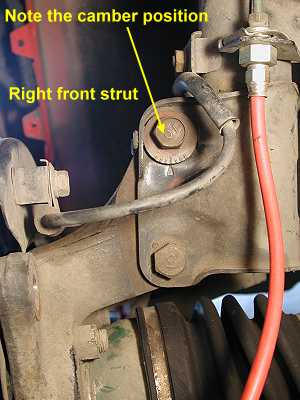
2. Support the lower arm. Snug a jack up against the lower arm. It is not necessary to raise the arm and strut.
3. Brackets. Remove the 12-mm nut and lock washer on the ABS speed sensor bracket and the 12-mm bolt and lock washer on the brake hose tube clamp. I had the calipers off the rotors for painting when I performed the strut removal the first time. However, you can leave the caliper on without problem.
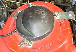
4. Upper mounting nuts. Remove the three 14-mm upper mounting nuts. Gently pry up on the ECS cap to release it. Underneath is the same type of plugin ECS connector that is on the rear shocks. If squeezing on the sides of the connector does not release it then use a 1/8" screwdriver or similar tool to gently pry out on the connector where it snaps into the notch in the piston rod, while at the same time exerting slight upward force with your other hand on the connector itself (see picture above). Set the connector and cap aside.
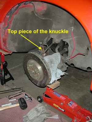
5. Lower mounting bolts. Place a rag or other barrier on top of the driveshaft boot under the strut. Loosen and remove if you can the bottom 17-mm lower mounting nut. You may have to stop the bolt from turning with a 17-mm wrench. You may also need a breaker bar to loosen both the bottom and top lower mounting nuts. Remove the top nut and bolt. You may have to lower or raise the hub and strut to relieve pressure on the bolts for removal. A mallet can also be helpful. You may also need the mallet to free the strut from the knuckle. Once free, move the bottom of the strut to the rear and down. Bring the top of the strut out first.
Front Strut Disassembly
1. Self locking nut and spring. The manual recommends loosening the self locking nut (but not removing!) before compressing the spring. There is a special tool that attaches to the spring upper seat to keep the piston rod from turning. The spring upper seat can also be placed carefully in a vice to loosen the nut. I found that I could not compress the springs sufficiently to relieve pressure on the upper seat. So I took both struts to Midas Muffler to have them compress the spring and remove the nut. Alternatively, and I do not suggest or recommend this, you could remove the nut while there is some spring pressure left on the upper seat. This is very dangerous as the nut may be propelled rapidly away from the strut. Be sure the strut is pointed in a safe direction if you elect to use this dangerous method.
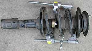
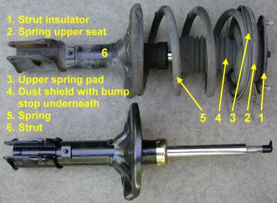
3. Disassemble strut components. After the nut is removed, the rest of the parts are taken off by hand. The bump stop is inside of the dust cover and the two pieces must be pried apart if you want to separate them. Transfer the parts you need to your new shock. Use the spring compressor if needed before attaching the upper seat, insulator, and retaining nut. I did not reassemble the strut with the stock spring (I replaced it with a Ground Control spring that does not need to be compressed). Be sure you can compress the spring suficiently to re-attach the nut and still be able to remove your spring compressor tool. Torque the retaining nut to 56 ft-lb (78 Nm). Without the special tool, I held the upper seat in a vice in order to tighten the retaining nut. Be sure the notch on the piston rod is exposed for the ECS connector to lock into it.
Rear Shock Installation
If you have trouble with rust, use some anti-seize compound on the mounting nuts and bolts.
1. Prepare the lower mounting post. Check the threads of the lower mounting post. The 17-mm bolt should thread into the post by hand. If there is significant reistance, then the threads of the post or the bolt must be cleaned up. I slightly damaged the outermost threads of my right mounting post with the gear puller. A 12mm x 1.25 pitch tap was not easy to find, so I purchased some 12x1.25 steel bolts that could be sacrificed cleaning the threads of the post. After the threads are ready, apply some high-temperature, heavy-load grease to the outside of the post. This may delay the rust that can "weld" the inner bushing to the post.
2. Attach the shock. Insert the upper two mounting bolts. Compress the shock a little and slide the lower bushing onto the mounting post. Note that the metal lower bushing has a wide, tapered end that slides on first.
3. Bolt the shock in. Using a new 12-mm lock washer, attach the lower bolt and torque to 72 ft-lb (100 Nm). Attach the two upper mounting nuts and torque them to 33 ft-lb (45 Nm). Connect the ECS connector; be sure it locks in. Pull the ECS harness through the cap and snap the cap on. Attach the ECS harness retaining nut.
Front Strut Installation
If you have trouble with rust, use some anti-seize compound on the mounting nuts and bolts.
1. Upper mount. Insert the bottom of the strut into the space rearward of the knuckle and then bring the top in. lift the strut up and insert the insulator bolts into the three holes in the fender and hold the strut there with one hand. With your other hand attach the nuts to the bolts and tighten them finger tight.
2. Lower mounting bolts. The jack should still be supporting the hub. Align the lower mounting bolt holes with the holes in the knuckle (the jack can help). Using new 12-mm lock washers, slide the lower bolts in and tighten the nuts by hand. Align the camber marks on the top bolt with arrow on the strut as they were before you removed the strut. Holding the bolt in place with a wrench, tighten the nut to 65-76 ft-lb (90-105 Nm). Now tighten the bottom nut and bolt (I used the same torque specification).
3. Upper mount (again). With the jack still supporting the hub and strut, remove the three upper mounting nuts. Attach the ECS connector to the piston rod. Put the cap in place and add the three nuts, torquing them to 33 ft-lb (45 Nm).
4. Brackets. Re-attach the ABS speed sensor bracket and the 12-mm bolt and lock washer on the brake hose tube clamp. Put the calipers back on if you removed them.
Post-installation
Double check that you have tightened all nuts and bolts. Put the wheels back on the car and lower the car to the ground. You will need to have the wheel alignment checked and adjusted if necessary.
Page last updated March 17, 2002.

