Fuel Injector Duty Cycle Calculator

by Jeff Lucius

The fuel injector duty cycle (IDC) is the percentage of time the injector is supplied with power. The time during which the injector is powered (or activated) is called the injector pulse width (IPW). During normal engine operation, the fuel injector fires once during the four strokes of the Otto cycle, which last for 2 revolutions of the engine. As an example, at 3000 rpm it takes 0.040 seconds or 40 milliseconds (ms) for the engine to complete 2 revolutions (3000 rpm divided by 60 equals 50 revs per second; invert to get 0.02 sec per rev or 0.04 second for 2 revs). At 6000 rpm it takes 20 ms for two revolutions. If a fuel injector is activated for 15 ms (the IPW) at 3000 rpm the duty cycle is 37.5% (15 ms/40 ms), or rpm times IPW divided by 1200 equals IDC in percent. If an injector is powered for 15 ms at 6000 rpm, then IDC is 75% (15 ms/20 ms). If you know the engine speed (rpm) and the IPW (dataloggers can provide this information), then it is easy to calculate the IDC.

NOTE: These calculators were originally developed many years ago in Internet Explorer.

For those of you with IE 7 (or beyond), you may get a warning about my web site using ActiveX controls. It does not. I do use JavaScript for my calculators. If you want the functionality of the calculators, allow "ActiveX" controls (see instructions by clicking on the IE bar above my web page, if it is there).


You can use the calculator below to determine injector duty cycle when engine speed and injector pulse width are known. You can enter numbers in the white boxes. The yellow box shows the result and is read-only. The "Reset fields" button writes the default values into the white boxes. Press "Calculate" to determine IDC. To change the value in a white box, first click in the box to give it the mouse/keyboard focus. Then change the number. Letters are not allowed; neither are negative values. Click outside the box or click the "Calculate" button to show the IDC. This simple calculator is illustrative but not very interesting. The calculators in the next section are much more useful.

   RPM       IPW (ms)    IDC  


Input parameters
Air/Fuel Ratio Limits
   6.0:1
   9.0:1
 11.5:1
 12.5:1
 13.2:1
 14.7:1
 15.5:1
 16.2:1
 18-22:1
 Rich run limit 
 Low power, black smoke 
 Rich best torque at WOT 
 Safe best power at WOT 
 Lean best torque at WOT 
 Chemically ideal 
 Lean light load, part throttle 
 Best economy, part throttle 
 Lean run limit 
 

As we modify our engines to produce more power, we install larger fuel injectors. The calculators and information below can assist in determining the correct injector size to reach your goals by presenting the required duty cycles for different sized injectors during various engine loads (mass air flow divided by engine speed). The boost value is the major factor determining engine load.

The engine control module (ECM) determines the injector pulse width using many engine sensors and a variety of control logic depending on engine operating conditions (see 2-fuelinjection.htm for more details). When engine power is more important than fuel economy, the most important input is the engine speed (from the crank angle sensor), the mass air-flow rate (from the volume air-flow, air-temperature, and air-pressure sensors), and the target air-fuel ratio (A/F; determined from tables programmed into the ECM).

When we install larger-than-stock fuel injectors, we usually install the ability to alter the air-fuel ratio using some sort of controller. While we would like to keep A/F near 12.5 for best power, the A/F usually must be lowered (the mixture richened) to reduce the tendency for detonation (knock). Quite often, this means A/F must be near 11 or a little lower. The table above shows typical A/F limits for different engine operating conditions. You can select an A/F in the input parameters below. While 12 is the default, I suggest lowering this to about 11 to simulate real fuel demands during WOT engine operation at high boost levels.

We need to know the A/F here because after the mass air flow is determined for a particular engine speed (see below) the A/F and gasoline density are used to determine the volume of fuel required. The average value for the density of gasoline is usually stated as 6 pounds per gallon, equivalent to 719 grams per liter. You should probably leave the gasoline density at the default value unless you know the value for the gasoline you use or just want to experiment. Knowing the required fuel volume and the maximum amount of fuel that the given number of injectors of the selected flow rate can flow if open constantly, the required injector duty cycle can be calculated.

While the ECM uses measured air flow, we will have to estimate air flow at various engine speeds. To do this we must know the volumetric efficiency of the engine during wide-open throttle (WOT) operation. Volumetric efficiency (VE) is the ratio of volume of air entering the air filter(s) to the engine displacement for each Otto cycle. For forced induction engines, VE can easily exceed 100%. Again, because we cannot measure air flow here, I'll use a concept I call natural capacity (NC) and the pressure ratio to determine the air flow. Natural capacity is the percentage of cylinder swept area (or the engine displacement when considering all cylinders) that is replaced with fresh air-fuel charge, regardless of the air density (boost or vacuum), during the Otto cycle. The NC cannot be less than 0 nor more than 1.0 (100%). After all, you can only fill a cylinder completely and that's it. Pressure ratio is the absolute pressure in the plenum (ambient air pressure plus boost pressure) divided by the ambient air pressure (barometric pressure). Volumetric efficiency, then, is estimated as the natural capacity times the pressure ratio.

The set of default natural capacities in the calculator below are ones I have found to be reasonable for stock and for modified engines. The values can be changed by clicking the mouse inside one of the white boxes and modifying the value to be from 0.0 to 1.0. Click "Re-calculate" to update the IDC tables. You can set all the "Modified" natural capacities to 1.0 (100%) to simulate a perfect flowing engine (even if nearly impossible to attain); this would be the very maximum amount of air an engine could flow for a given pressure ratio and engine speed. Clicking the "Reset fields" button restores the default NC values; but the "Re-Calculate" button must be clicked to change the IDC tables.

Intake air temperature ºF (at air filter) ºC        
Intake air pressure psi (at air filter) in. Hg kg/cm2  bar
Air density g/l (at air filter) g/CF lb/CF    
Gasoline density g/l (typical is 690 to 760)  lb/gal        
Engine displacement liters   CI        
Air-Fuel ratio A/F (typical is 6 to 22)            
Injector rated flow cc/min at 43 psi lb/hr        
Number of injectors                
Boost pressure psi (at plenum) kg/cm2  bar kPa
Pressure ratio                


Natural Capacities
rpm 3000 4000 5000 6000 7000 8000      
Stock    
Modified    


IDC for a single user-selected injector size

As in the first little calculator above, the yellow boxes are for display only and cannot be edited. Change values in the white boxes above and click the "Calculate" button to update these tables. Using the radio buttons, you can select between the natural capacities for a stock engine or for a modifed engine.

Many manufacturers recommend that IDC does not remain above 85-90% for extended periods. Some injectors may actually flow less above 95% IDC than below that value. Of course, if the listed IDC is greater than 100%, the fuel injector is inadequate for the application.

RPM NC lph IDC%
3000       cc/min Injector Rated Flow
4000       psi Boost
5000       A/F Air-fuel ratio
6000       g/l Air Density
7000       g/l Gasoline Density
8000       liters Engine Displacement
            Stock engine NC
            Modified engine NC


IDC for a several pre-selected injector sizes

As above, the yellow boxes are for display only and cannot be edited. Change values in the white boxes above and click the "Calculate" button to update these tables. Only natural capacities for modified engines are used here. To change these, change values in the Natural Capacities form above and press the "Re-calculate" button. The factory fuel injectors are rated at 360 cc/min. DSM (Eclipse, Laser, and Talon) turbo models had 450 cc/min injectors. The new Mitsubishi Lancer Evolution VIII has fuel injectors that are reported to flow about 580 cc/min and also have the dual port pintle opening. The aftermarket 660 cc/min and larger injectors are popular for the highest output 3000GT/Stealth engines.

Inj. rated flow (cc/min) 360 450 520 550 580 625 660 720 850
RPM NC lph Injector Duty Cycle %
3000
4000
5000
6000
7000
8000
Boost psi     PR        
Air-fuel ratio A/F              
Air Density g/l   IAT ºF   Baro psi
Gasoline Density g/l              
Engine Displacement liters   Inj's.        


Selecting the right-size fuel pump

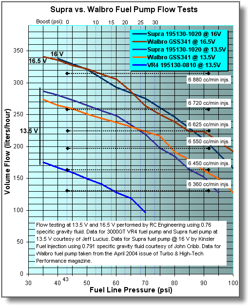
The required fuel flow values, in the "lph" column in the tables above, can be used to determine the "size" fuel pump needed. The chart below shows flow data for two of the most popular upgrade fuel pumps for 3000GT/Stealth cars. For additional fuel pump upgrade information see my web page 2-fuelpumpguide.htm. To determine if a fuel pump with a provided voltage can provide the required fuel, first note the "lph" flow at an rpm and boost level in a table above. Find this lph flow on the left axis in the chart below. On the top axis of the chart below find the chosen boost level. Locate the intersection of these two "lines". If the fuel pump flow curve lies above this value, the fuel pump should be able to satisfy the engine demands.

Comparison of VR4, Supra, and Walbro fuel pumps


Back Home Forward
Except for the small gif and jpg images, the content, images, photographs, text, and multimedia displayed are Copyright ©2000-2005 by Jeff Lucius and K2 Software. All rights reserved. No part, section, image, photo, article, or whole of this site may be reposted or redisplayed without permission of the author.
Page last updated March 21, 2007.